Dell Alienware M17x Service Manual - Page 91
consumer IR cable connector on system, board, screws 5, IR board, system board
 |
UPC - 074450000071
View all Dell Alienware M17x manuals
Add to My Manuals
Save this manual to your list of manuals |
Page 91 highlights
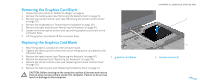
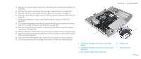
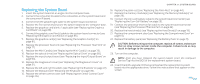
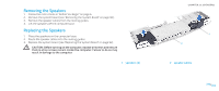
13. Remove the input/output board (see "Removing the Input/Output Board" on page 62). 14. Remove the optical drive (see "Removing the Optical Drive" on page 66). 15. Remove the Mini-Card(s) (see "Removing the Mini-Card(s)" on page 71). 16. Remove the processor heat sink (see "Removing the Processor Heat Sink" on page 76). 17. Remove the graphics card(s) (see "Removing the Graphics Card(s)" on page 80). 18. Disconnect the graphics card fan(s) cable from the system board connector (see "Removing the Graphics Card Fan(s)" on page 84). 19. Remove the graphics card blank, if applicable (see "Removing the Graphics Card Blank" on page 88). 20. Remove the five screws that secure the system board to the computer base. 21. Disconnect the consumer IR cable from the connectors on the system board and consumer IR board. 22. Disconnect the left speaker light cable from the system board connector. 23. Lift the system board at an angle and remove it from the computer base. 5 4 3 1 consumer IR cable connector on system board 2 consumer IR cable connector on consumer IR board 3 left speaker light cable connector CHAPTER 21: SYSTEM BOARD 1 2 4 screws (5) 5 system board 091 /091
-
 1
1 -
2
-
3
-
4
-
5
-
6
-
7
-
8
-
9
-
10
-
11
-
12
-
13
-
14
-
15
-
16
-
17
-
18
-
19
-
20
-
21
-
22
-
23
-
24
-
25
-
26
-
27
-
28
-
29
-
30
-
31
-
32
-
33
-
34
-
35
-
36
-
37
-
38
-
39
-
40
-
41
-
42
-
43
-
44
-
45
-
46
-
47
-
48
-
49
-
50
-
51
-
52
-
53
-
54
-
55
-
56
-
57
-
58
-
59
-
60
-
61
-
62
-
63
-
64
-
65
-
66
-
67
-
68
-
69
-
70
-
71
-
72
-
73
-
74
-
75
-
76
-
77
-
78
-
79
-
80
-
81
-
82
-
83
-
84
-
85
-
 86
86 -
 87
87 -
 88
88 -
 89
89 -
 90
90 -
 91
91 -
 92
92 -
 93
93 -
 94
94 -
 95
95 -
 96
96 -
97
-
98
-
99
-
100
-
101
-
102
-
103
-
104
 |
 |
