Dell CX4 Troubleshooting Guide - Page 29
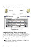
end fibre channel port on SP-A., Connect a cable from Fibre Channel switch 0 sw0 to the first front - + - 120 c
 |
View all Dell CX4 manuals
Add to My Manuals
Save this manual to your list of manuals |
Page 29 highlights
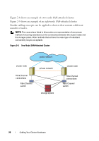
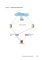
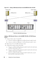
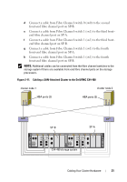
Cabling a SAN-Attached Cluster to a Dell/EMC CX4-120 or CX4-240 Storage System 1 Connect cluster node 1 to the SAN: a Connect a cable from HBA port 0 to Fibre Channel switch 0 (sw0). b Connect a cable from HBA port 1 to Fibre Channel switch 1 (sw1). 2 Repeat step 1 for each additional cluster node. 3 Connect the storage system to the SAN: a Connect a cable from Fibre Channel switch 0 (sw0) to the first frontend fibre channel port on SP-A. b Connect a cable from Fibre Channel switch 0 (sw0) to the first frontend fibre channel port on SP-B. c Connect a cable from Fibre Channel switch 1 (sw1) to the second front-end fibre channel port on SP-A. d Connect a cable from Fibre Channel switch 1 (sw1) to the second front-end fibre channel port on SP-B. NOTE: Additional cables can be connected from the fibre channel switches to the storage system if there are available front-end fibre channel ports on the storage processors. Cabling Your Cluster Hardware 29
-
 1
1 -
2
-
3
-
4
-
5
-
6
-
7
-
8
-
9
-
10
-
11
-
12
-
13
-
14
-
15
-
16
-
17
-
18
-
19
-
20
-
21
-
22
-
23
-
 24
24 -
 25
25 -
 26
26 -
 27
27 -
 28
28 -
 29
29 -
 30
30 -
 31
31 -
 32
32 -
 33
33 -
 34
34 -
35
-
36
-
37
-
38
-
39
-
40
-
41
-
42
-
43
-
44
-
45
-
46
-
47
-
48
-
49
-
50
-
51
-
52
-
53
-
54
-
55
-
56
-
57
-
58
-
59
-
60
-
61
-
62
-
63
-
64
-
65
-
66
-
67
-
68
 |
 |