Dell CX4 Troubleshooting Guide - Page 32
Dell Cluster, Configuration Support Matrix, For rules and guidelines for SAN-attached clusters
 |
View all Dell CX4 manuals
Add to My Manuals
Save this manual to your list of manuals |
Page 32 highlights
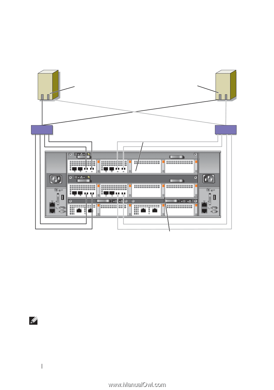
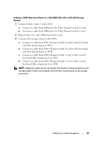
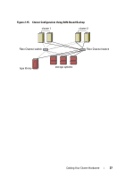
Figure 2-12. Cabling a SAN-Attached Cluster to the Dell\EMC CX4-960 cluster node 1 cluster node 2 HBA ports (2) 01 HBA ports (2) 01 sw0 Fibre Channel switch SP-B Fibre Channel switch sw1 0 1 23 0 1 23 0 1 23 0 1 23 0 1 0 1 CX4-960 storage system SP-A Cabling Multiple SAN-Attached Clusters to a Dell/EMC Storage System To cable multiple clusters to the storage system, connect the cluster nodes to the appropriate Fibre Channel switches and then connect the Fibre Channel switches to the appropriate storage processors on the processor enclosure. For rules and guidelines for SAN-attached clusters, see the Dell Cluster Configuration Support Matrix on the Dell High Availability website at www.dell.com/ha. NOTE: The following procedures use Figure 2-10, Figure 2-11, and Figure 2-12 as examples for cabling additional clusters. 32 Cabling Your Cluster Hardware
-
 1
1 -
2
-
3
-
4
-
5
-
6
-
7
-
8
-
9
-
10
-
11
-
12
-
13
-
14
-
15
-
16
-
17
-
18
-
19
-
20
-
21
-
22
-
23
-
24
-
25
-
26
-
 27
27 -
 28
28 -
 29
29 -
 30
30 -
 31
31 -
 32
32 -
 33
33 -
 34
34 -
 35
35 -
 36
36 -
 37
37 -
38
-
39
-
40
-
41
-
42
-
43
-
44
-
45
-
46
-
47
-
48
-
49
-
50
-
51
-
52
-
53
-
54
-
55
-
56
-
57
-
58
-
59
-
60
-
61
-
62
-
63
-
64
-
65
-
66
-
67
-
68
 |
 |