Dell Force10 C300 C300 Hardware Installation Guide
Dell Force10 C300 Manual
 |
View all Dell Force10 C300 manuals
Add to My Manuals
Save this manual to your list of manuals |
Dell Force10 C300 manual content summary:
- Dell Force10 C300 | C300 Hardware Installation Guide - Page 1
Installing and Maintaining the C300 System - Dell Force10 C300 | C300 Hardware Installation Guide - Page 2
damage to hardware or loss of data if instructions are not followed. WARNING: A WARNING indicates a potentia for property damage, personal injury, or death. Information in this publication is subject to change without notice. © 2012 Dell Force10. All rights reserved. Reproduction of these materials - Dell Force10 C300 | C300 Hardware Installation Guide - Page 3
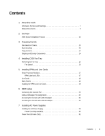
RPMs and Line Cards 18 6 RPM Cables Connecting the Console Port 23 Cable and Adapter Pin Assignments 23 Accessing the Console with a DB-9 Adapter 24 Accessing the Console with a DB-25 Adapter 24 7 Installing AC Power Supplies Installing the AC Power Supply 29 Power Cord Requirements 30 Power - Dell Force10 C300 | C300 Hardware Installation Guide - Page 4
www.dell.com | support.dell.com 8 Installing DC Power Entry Modules Recommended Normal Operating Conditions 33 Redundancy 33 Cable and Connector Requirements 34 Installing a DC PEM 34 Status LED 37 Removing a DC PEM 37 9 Powering Up Supplying 39 Booting from the BOOT_USER Prompt 41 10 - Dell Force10 C300 | C300 Hardware Installation Guide - Page 5
Electromagnetic Compatibility (EMC 66 Product Recycling and Disposal 66 C Contacting Technical Support The iSupport Website 69 Accessing iSupport Services 69 Contacting the Technical Assistance Center 69 Locating Serial Numbers 70 Requesting a Hardware Replacement 70 Contents | 5 - Dell Force10 C300 | C300 Hardware Installation Guide - Page 6
www.dell.com | support.dell.com 6 | Contents - Dell Force10 C300 | C300 Hardware Installation Guide - Page 7
and instructions for installing the Dell Force10 C300 chassis, fan tray, power supply units (supplies), route processor modules (RPMs), and line cards. The C300 system is packaged with all of the necessary components, including slot blanks for RPMs, power supplies, and line cards. Information - Dell Force10 C300 | C300 Hardware Installation Guide - Page 8
mehr als 240 V Wechselstrom, 10 A (bzw. in den USA 120 V Wechselstrom, 15 A) an den Phasenleitern (allen stromführenden Leitern) verwendet wird. WARNING: Building Supply Notice for DC Supply Use: An external disconnect must be provided and be easily accessible. Dell Force10 recommends the use of - Dell Force10 C300 | C300 Hardware Installation Guide - Page 9
Related Documents For more information about the C300 system, refer to the following documents: • FTOS Command Reference for C-Series • FTOS Configuration Guide for C-Series About this Guide | 9 - Dell Force10 C300 | C300 Hardware Installation Guide - Page 10
10 | About this Guide www.dell.com | support.dell.com - Dell Force10 C300 | C300 Hardware Installation Guide - Page 11
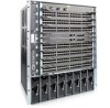
2 Overview The C300 is a high performance switch/router. The 10-slot system contains two slots for Route Processor Modules (RPMs) and eight slots for line cards. Figure 2-1. C300 Chassis (Front View) Front Mount Bracket 4-Port Fiber Line Card Fan Tray 0 1 2 3 R0 R1 4 SFM Status Master ACTIVE - Dell Force10 C300 | C300 Hardware Installation Guide - Page 12
www.dell.com | support.dell.com Table 2-1. C300 Component Requirements Component Minimum Backplane (factory installed) 1 Fan tray 1 RPM 1 Line card 1 AC Power Supply 2 DC Power Entry Module 2 Maximum 1 1 2 8 8 8 Field-Replaceable No Yes Yes Yes Yes Yes C300 System Installation - Dell Force10 C300 | C300 Hardware Installation Guide - Page 13
make sure that the area where you intend to install your C300 meets the following safety requirements: • It is in a restricted access area. • . • Allow at least 12 inches (30.5 cm) between two C300s or an C300 and another side airflow chassis. • Allow at least 18 inches in the front and 20 inches - Dell Force10 C300 | C300 Hardware Installation Guide - Page 14
used by the service in your area. • The AC cord is the primary ground. When you install the chassis, use a level to ensure the chassis is installed level. Requirements The C300 needs at least two supplies to operate. However, Dell Force10 recommends a two-plus-one redundancy configuration. That is - Dell Force10 C300 | C300 Hardware Installation Guide - Page 15
speed. For both types of trays, air flows through the C300 system toward the fans (right to left) and is exhausted on the fan-side of the chassis. The fan tray is accessible from the front of the chassis. Contact Dell Force10 Technical Support if you have questions concerning the fan tray for your - Dell Force10 C300 | C300 Hardware Installation Guide - Page 16
lit when the chassis is ed up and the fan tray is functioning properly. Removing the Fan Tray A fan tray failure or a failure of a fan within a fan tray is recognized by a red fan tray LED, a lit RPM alarm LED, and, if configured, an SNMP trap and alarm event. The failure requires a replacement of - Dell Force10 C300 | C300 Hardware Installation Guide - Page 17
Installing RPMs and Line Cards The C300 System accommodates eight line cards and two RPMs. Route Processor Modules The C300 system requires the installation of at least one Route Processor Module (RPM); two are recommended. • One RPM provides 48 Gigabits of bandwidth to each line card. • Two RPMs - Dell Force10 C300 | C300 Hardware Installation Guide - Page 18
be seen when the fan tray is installed. Line card LEDs are described in the documentation specific to each line card. Refer to the installation documentation that came with the card for to understand LED appearance and meaning. Blank Panels Blanks are required in empty slots to control airflow for - Dell Force10 C300 | C300 Hardware Installation Guide - Page 19
until the card is about halfway into the slot. NOTE: Use the markings on the fan tray to determine which slots are for the RPMs and which are for the line cards. 4 Continue sliding the line card until you feel the connectors engage with the chassis backplane. Installing RPMs and Line Cards | 19 - Dell Force10 C300 | C300 Hardware Installation Guide - Page 20
www.dell.com | support.dell.com Step Task 5 Rotate the levers towards the card to seat the backplane connectors and line card in place. Push on the knurled section of the levers until the thumb tabs pop up and lock the unit in place. See Figure 5-3 and - Dell Force10 C300 | C300 Hardware Installation Guide - Page 21
Figure 5-5. Installing a Line Card Card Guide Card Lever fnC0005mp Figure 5-6. Installing an RPM Card Lever Card Guide fnC0006mp Installing RPMs and Line Cards | 21 - Dell Force10 C300 | C300 Hardware Installation Guide - Page 22
www.dell.com | support.dell.com 22 | Installing RPMs and Line Cards - Dell Force10 C300 | C300 Hardware Installation Guide - Page 23
option set to NO • 24 lines X 80 characters • No flow control Cable and Adapter Pin Assignments Use the C300 System Console port on the RPM to connect to a terminal port, PC serial port, or a terminal server to configure and monitor your system. An RJ-45 Ethernet cable is required to connect to the - Dell Force10 C300 | C300 Hardware Installation Guide - Page 24
dell.com | support.dell.com Table 6-1. Console Port (RJ-45) Pin Assignments Pin Signal Input/Output 1 NC (unused) - 2 DTR Output 3 TxD Output 4 GND - 5 GND - 6 RxD Input 7 DSR Input 8 NC (unused) - Accessing the Console with a DB-9 Adapter You can connect to the console - Dell Force10 C300 | C300 Hardware Installation Guide - Page 25
-25 Adapter C300 System Console Port Signal RTS DTR TxD GND GND RxD DSR CTS RJ-45 to RJ-45 Rollover Cable RJ-45 Pinout 1 2 3 4 5 6 7 8 RJ-45 Pinout 8 7 6 5 4 3 2 1 RJ-45 to DB-25 Modem Adapter DB-25 Pinout 5 6 3 7 7 2 20 Terminal Server Device Signal CTS DSR RxD GND GND TxD DTR RTS RPM Cables - Dell Force10 C300 | C300 Hardware Installation Guide - Page 26
26 | RPM Cables www.dell.com | support.dell.com - Dell Force10 C300 | C300 Hardware Installation Guide - Page 27
Power Supply Units (PSUs) or DC Power Entry Modules (PEMs). • Dell Force10 does not support the use of a combination of AC and DC power supplies. • If you select AC, the C300 requires a minimum of two AC power supplies to operate, but Dell Force10 recommends a two-plus-one redundancy configuration - Dell Force10 C300 | C300 Hardware Installation Guide - Page 28
www.dell.com | support.dell.com Figure 7-1. Power Supply Location fnC0001mp 28 | Installing AC Power Supplies - Dell Force10 C300 | C300 Hardware Installation Guide - Page 29
in the power supply, it must be replaced. Power supplies are not field serviceable. Installing the AC Power Supply WARNING: Use only the power cord supplied with the power supply. Do not supply power to your C300 system until the power supplies, blank panels, fan tray, RPMs, and line cards have - Dell Force10 C300 | C300 Hardware Installation Guide - Page 30
3 primary + 1 redundant NOTE: For system input power requirements see System Specifications on page 62. You can install any AC power supply into any power supply slot. Dell Force10 recommends installing power supplies starting from the left side of the chassis, leaving no blank slots between units - Dell Force10 C300 | C300 Hardware Installation Guide - Page 31
. A maximum of 15.4 Watts (at 48 Volts) can be transmitted over a link. The chassis transmits power to connected IEEE 802.3af-compliant devices via ports that are enabled with PoE. A minimum of four AC power supplies are required to enable PoE, and 77 ports can be enabled per PSU, starting at the - Dell Force10 C300 | C300 Hardware Installation Guide - Page 32
32 | Installing AC Power Supplies www.dell.com | support.dell.com - Dell Force10 C300 | C300 Hardware Installation Guide - Page 33
redundancy configuration. Those DC PEMs are inserted in slots 0 and 7. • To protect against high-voltage shock, install a supply blank (CC-C-BLNK-PWR) on all unused supply slots. NOTE: The C300 DC Power Entry Module does not support PoE line cards. NOTE: Some CH-C300 chassis may require Dell Force10 - Dell Force10 C300 | C300 Hardware Installation Guide - Page 34
www.dell.com | support.dell.com fn003lp Cable and Connector Requirements You must provide your own cables to connect to a remote source (a circuit breaker panel, for example) in your equipment rack or facility. Cables must be sized to meet the following criteria: • Rated for 60A service to allow - Dell Force10 C300 | C300 Hardware Installation Guide - Page 35
any other PEM connection. Locate the chassis ground connector stud on the PEM front panel (see Figure 8-3). It is the single stud below the safety cover. Remove the nut and washer from the ground stud. Apply a coat of anti-oxidant paste to the connector stud, if required. Install the grounding cable - Dell Force10 C300 | C300 Hardware Installation Guide - Page 36
.dell.com | support.dell . Apply a coat of anti-oxidant paste to the connector studs, if required. Replace the washers and nuts on the studs. Route the terminated cables that the safety cover can be rotated to accommodate system configurations. 10 Turn the Over-Current Protector to the ON position ( - Dell Force10 C300 | C300 Hardware Installation Guide - Page 37
normally. Removing a DC PEM The left chassis PEM slot is labelled "0" and the right chassis PEM slot is labelled "1." For full to operate this system with the safety cover removed. Step Task 1 Switch the Over Current Protector (located on the PEM front panel) to DC Power Entry Modules | 37 - Dell Force10 C300 | C300 Hardware Installation Guide - Page 38
www.dell.com | support.dell.com 38 | Installing DC Power Entry Modules - Dell Force10 C300 | C300 Hardware Installation Guide - Page 39
All line cards and RPMs are properly installed and secured. • All chassis slots are filled. Blank panels and covers are installed in all empty slots. • Make sure no objects are placed on top of the unit. • Make sure the equipment is properly grounded. Supplying WARNING: Never operate the C300 System - Dell Force10 C300 | C300 Hardware Installation Guide - Page 40
is receiving and is operational. When you supply to the C300, the system performs a series of -on self tests. RPM and line card LEDs blink as the diagnostic programs run. No user interaction is required at this point. Observe the process on your console monitor. When the boot process is complete - Dell Force10 C300 | C300 Hardware Installation Guide - Page 41
automatically brings up the system to the runtime CLI. To interrupt the automatic boot process, issue a break key sequence (CNTL ^ or CNTL~ ). The console monitor will display the default BOOT_USER # prompt. Refer to "Alarms" on page 59 for instructions to continue the boot process. Powering Up | 41 - Dell Force10 C300 | C300 Hardware Installation Guide - Page 42
42 | Powering Up www.dell.com | support.dell.com - Dell Force10 C300 | C300 Hardware Installation Guide - Page 43
Power Supply Units • Removing and Replacing a Line Card When a component fails, the C300 System system triggers an alarm LED (located on the active RPM), disables or changes component Status LEDs, and sends events to the SNMP trap and show alarms table (if this feature is configured). Refer - Dell Force10 C300 | C300 Hardware Installation Guide - Page 44
in the empty slot. Blanks are required to control airflow and electromagnetic interference. A power supply failure is recognized by a red LED, a lit RPM alarm LED, and, if configured, an SNMP trap. If you are operating your C300 chassis with a redundant power supply, you can install, remove, or - Dell Force10 C300 | C300 Hardware Installation Guide - Page 45
Figure 8-2 and Figure 8-3 for a visual reference. 10 Plug the AC power cord into an AC outlet, if applicable. 11 Toggle the switch on the power supply to the ON (top) position. 12 Turn up the chassis if necessary. Removing and Replacing a Line Card WARNING: Do not remove a panel blank unless - Dell Force10 C300 | C300 Hardware Installation Guide - Page 46
the instructions in Installing the RPMs and Line Cards on page 18. Removing and Replacing an RPM WARNING: After removing an RPM, place a panel blank in the empty slot before powering up the chassis. Blanks are required to control airflow and electromagnetic interference. NOTE: The C300 requires at - Dell Force10 C300 | C300 Hardware Installation Guide - Page 47
and connector pins. 4 If you are not replacing the RPM, insert an RPM blank panel. 5 If you are replacing the RPM, follow the instructions in Installing the RPMs and Line Cards on page 18. 6 Only after the replacement is installed, power up the chassis. Removing and Replacing Components | 47 - Dell Force10 C300 | C300 Hardware Installation Guide - Page 48
www.dell.com | support.dell.com 48 | Removing and Replacing Components - Dell Force10 C300 | C300 Hardware Installation Guide - Page 49
lifting or moving the chassis. Install the chassis into the rack before inserting chassis components. Lift the C300 chassis only from the bottom. Lifting by the chassis shelves or power supply openings will damage the chassis. WARNING: To prevent bodily injury when mounting or servicing this unit in - Dell Force10 C300 | C300 Hardware Installation Guide - Page 50
www.dell.com | support.dell.com Step Task 1 Install the equipment rack bar. This bar enables you to easily position the chassis into the rack and stabilizes the chassis. • Orient the equipment rack bar at the desired location in the rack, with the arrows pointing up and the smooth side facing - Dell Force10 C300 | C300 Hardware Installation Guide - Page 51
Step Task 4 Insert screws (provided with your rack) through the chassis rack-mounting bracket and into the equipment rack, and tighten them (see Figure 11-2). Figure 11-2. Rack Mounting the Chassis fnC0009mp Installing the Chassis | 51 - Dell Force10 C300 | C300 Hardware Installation Guide - Page 52
52 | Installing the Chassis www.dell.com | support.dell.com - Dell Force10 C300 | C300 Hardware Installation Guide - Page 53
Boot When you supply power to the C300 system, the system performs a series of on self-tests. RPM and line card Status LEDs blink during initialization No user interaction is required as long as the boot process proceeds without interruption. Observe the process on your console monitor. When the - Dell Force10 C300 | C300 Hardware Installation Guide - Page 54
www.dell.com | support.dell.com To configure the chassis from the BOOT_USER prompt, use the following commands: Command help or ? boot change {primary | secondary | default} show bootvar show bootflash interface management port config 100m interface management port config 10m interface management - Dell Force10 C300 | C300 Hardware Installation Guide - Page 55
configuration. Reload the software. The autoboot program initializes and displays self-test results on the console screen. NOTE: Do not press the break control sequence at any time during the boot/reboot process. Doing so causes the boot process to terminate. Refer to the C-Series FTOS Command Line - Dell Force10 C300 | C300 Hardware Installation Guide - Page 56
56 | System Boot www.dell.com | support.dell.com - Dell Force10 C300 | C300 Hardware Installation Guide - Page 57
and then transfer the configuration to other C300 systems in your network. NOTE: Use only a Dell Force10 Compact memory card in your C300 System. Additional memory cards can be purchased from Dell Force10. Inserting the Compact Flash Card NOTE: Insert the Compact Flash Card either before system boot - Dell Force10 C300 | C300 Hardware Installation Guide - Page 58
be reformatted in the C300 flash slot before they can be used. Formatting erases all information stored on the flash card. To format the Compact Flash card: Step Task 1 Insert the flash card into the flash slot on the primary RPM. 2 In the CLI, enter format slot0: FTOS supports up to a 40 - Dell Force10 C300 | C300 Hardware Installation Guide - Page 59
on line cards A major alarm is any fault that would render the C300 System non-functional. A minor alarm is any fault that threatens the operation of the C300 System. You can monitor alarm conditions on the C300 System system through the console and LEDs. If you configure the SNMP command (snmp - Dell Force10 C300 | C300 Hardware Installation Guide - Page 60
www.dell.com | support.dell.com Table A-1. Alarm Events and Reporting Module Alarm Event Line Card Hardware failure Exceeds high temperature limit Exceeds warning temperature limit Individual interface fails RPM (Non-redundant Configuration with 1 RPM) Exceeds high temperature limit - Dell Force10 C300 | C300 Hardware Installation Guide - Page 61
B System Specifications Physical Design Chassis Dimensions Table B-1. Chassis Dimensions Parameter Height Width Depth Weight Mounting Clearance required Specifications 22.7 inches (57.66 cm) 17.4 inches (37.58 cm) 14.4 inches (44.20 cm) 55 lbs (24.95 kg) with factory installed components 152. - Dell Force10 C300 | C300 Hardware Installation Guide - Page 62
1G PoE Line Card 46-port FlexMedia Line Card 46-port FlexMedia PoE Line Card C300 RPM Fan Tray Supply Unit Line Card Blank Panel RPM Blank Panel PSU Blank Panel Catalog Number LC-CB-GE-48T LC-CB-10GE-4P LC-CB-10GE-8P LC-CB-GE-48P LC-CB-GE-48V LC-CB-10G-1G-36T LC-CB-10G-1G-36V LC-CB-RPM CC-C300-FAN - Dell Force10 C300 | C300 Hardware Installation Guide - Page 63
LC-CB-10GE-4P LC-CB-10GE-8P LC-CB-1GE-48P LC-CB-GE-48V LC-CB-10G-1G-36T LC-CB-10G-1G-36V LC-CB-RPM CC-C300-FAN CC-C-1200W-AC CC-C-PWR-DC Maximum Watts 150W 150W 200W 130 150W 120W 120W 165W 90W 1200W 1400W NOTE: The listed requirement for the PoE version of line cards excludes the required power - Dell Force10 C300 | C300 Hardware Installation Guide - Page 64
States relating to electromagnetic compatibility. Force 10 Networks can not accept responsibility for any failure to satisfy the protection requirements resulting from a non-recommended modification of this product, including the fitting of non-Dell Force10 option cards. This product has been tested - Dell Force10 C300 | C300 Hardware Installation Guide - Page 65
1st Edition • EN 60825-1, 1st Edition • EN 60825-1 Safety of Laser Products-Part 1: Equipment Classification Requirements and User's Guide • EN 60825-2 Safety of Laser Products-Part 2: Safety of Optical Fibre Communication Systems • FDA Regulation 21CFR 1040.10 and 1040.11 System Specifications | 65 - Dell Force10 C300 | C300 Hardware Installation Guide - Page 66
of product return programs and services in several countries to assist equipment owners in recycling their IT products. Waste Electrical and Electronic Equipment (WEEE) Directive for Recovery, Recycle and Reuse of IT and Telecommunications Products Dell Force10 switches are labeled in accordance - Dell Force10 C300 | C300 Hardware Installation Guide - Page 67
required by WEEE. For information on Dell Force10 product recycling offerings, see the WEEE Recycling instructions on iSupport at: https://www.force10networks.com/CSPortal20/Support/WEEEandRecycling.pdf. For more information, contact the Dell Force10 Perchlorate Materials. System Specifications | 67 - Dell Force10 C300 | C300 Hardware Installation Guide - Page 68
68 | System Specifications www.dell.com | support.dell.com - Dell Force10 C300 | C300 Hardware Installation Guide - Page 69
your Technical Assistance Center (TAC) cases. Dell Force10 iSupport provides integrated, secure access to these services. Accessing iSupport Services The URL for iSupport is www.force10networks.com/support/. To access iSupport services you must have a userid and password. If you do not have one, you - Dell Force10 C300 | C300 Hardware Installation Guide - Page 70
trace hardware command output • for line card issues, the show trace hardware linecard command output • console captures showing any error messages • console captures showing the troubleshooting steps taken • saved messages to a syslog server, if one is used • The support representative will - Dell Force10 C300 | C300 Hardware Installation Guide - Page 71
component, follow the packing and shipping directions in the Return Instructions document that accompanies the replacement component. Alternatively, contact your TAC representative for a replacement copy. Generally, you are instructed to return the RMA component in the original packaging material - Dell Force10 C300 | C300 Hardware Installation Guide - Page 72
www.dell.com | support.dell.com 72 | Contacting Technical Support - Dell Force10 C300 | C300 Hardware Installation Guide - Page 73
- Dell Force10 C300 | C300 Hardware Installation Guide - Page 74
Printed in the U.S.A. www.dell.com | support.dell.com
-
 1
1 -
 2
2 -
 3
3 -
 4
4 -
 5
5 -
 6
6 -
 7
7 -
8
-
9
-
10
-
11
-
12
-
13
-
14
-
15
-
16
-
17
-
18
-
19
-
20
-
21
-
22
-
23
-
24
-
25
-
26
-
27
-
28
-
29
-
30
-
31
-
32
-
33
-
34
-
35
-
36
-
37
-
38
-
39
-
40
-
41
-
42
-
43
-
44
-
45
-
46
-
47
-
48
-
49
-
50
-
51
-
52
-
53
-
54
-
55
-
56
-
57
-
58
-
59
-
60
-
61
-
62
-
63
-
64
-
65
-
66
-
67
-
68
-
69
-
70
-
71
-
72
-
73
-
74
 |
 |

Installing and Maintaining
the C300 System