Dell Force10 C300 C300 Hardware Installation Guide - Page 35
Insert 2 DC PEMs in Slots 0 and 7, WARNING
 |
View all Dell Force10 C300 manuals
Add to My Manuals
Save this manual to your list of manuals |
Page 35 highlights
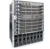
Step 4 Task (continued) Slide the PEM into slot 0 or 7 (see (Figure 8-2). If you are installing redundant PEMs, install in both slots 0 and 7. NOTE: Fill all empty slots with blank panels (CC-C-BLNK-PWR). Figure 8-2. Insert 2 DC PEMs in Slots 0 and 7 fn0002lp 5 Secure the PEM in place by tightening the retaining latch on each module so that the arrow points down (Figure 8-2). 6 Secure the chassis ground connection: WARNING: You must complete the ground connection before proceeding with any other PEM connection. Locate the chassis ground connector stud on the PEM front panel (see Figure 8-3). It is the single stud below the safety cover. Remove the nut and washer from the ground stud. Apply a coat of anti-oxidant paste to the connector stud, if required. Install the grounding cable. This cable is typically green or green and yellow. NOTE: Termination points require UL-listed 1-hole lug with a 1/4-inch hole. Replace the washer and nut on the stud. Secure the nut with a nut driver or torque wrench (not to exceed 4 ft/lbs). Connect the opposite end of the grounding cable to the appropriate nearest grounding. Installing DC Power Entry Modules | 35
-
 1
1 -
2
-
3
-
4
-
5
-
6
-
7
-
8
-
9
-
10
-
11
-
12
-
13
-
14
-
15
-
16
-
17
-
18
-
19
-
20
-
21
-
22
-
23
-
24
-
25
-
26
-
27
-
28
-
29
-
 30
30 -
 31
31 -
 32
32 -
 33
33 -
 34
34 -
 35
35 -
 36
36 -
 37
37 -
 38
38 -
 39
39 -
 40
40 -
41
-
42
-
43
-
44
-
45
-
46
-
47
-
48
-
49
-
50
-
51
-
52
-
53
-
54
-
55
-
56
-
57
-
58
-
59
-
60
-
61
-
62
-
63
-
64
-
65
-
66
-
67
-
68
-
69
-
70
-
71
-
72
-
73
-
74
 |
 |
