Dell Force10 C300 C300 Hardware Installation Guide - Page 33
Installing DC Power Entry Modules, Recommended Normal Operating Conditions, Redundancy
 |
View all Dell Force10 C300 manuals
Add to My Manuals
Save this manual to your list of manuals |
Page 33 highlights
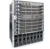
8 Installing DC Power Entry Modules The C300 has eight supply slots at the front-bottom of the chassis (Figure 8-2 on page 35). The slots accept either AC Power Supplies (PSUs) or DC Power Entry Modules (PEMs). Dell Force10 does not support the use of a combination of AC and DC. • If you select DC, the C300 requires at least one DC PEM for operation, but Dell Force10 recommends a one-plus-one redundancy configuration. Those DC PEMs are inserted in slots 0 and 7. • To protect against high-voltage shock, install a supply blank (CC-C-BLNK-PWR) on all unused supply slots. NOTE: The C300 DC Power Entry Module does not support PoE line cards. NOTE: Some CH-C300 chassis may require Dell Force10 assistance when using some DC power supplies. Please contact the Dell Force10 TAC if you experience any difficulty during installation. Recommended Normal Operating Conditions Table 8-1. Input voltage Input Ranges -44V (minimum) -48V (typical) -55V (maximum) Table 8-2. Operating Ranges Ambient Temperature Operating Range Storage Range Humidity Operating Range Storage Range -5° C to +40° C -40° C to +70 ° C 5-85% RH 5-90% RH Maximum 1408 watts 1536 watts 1760 watts Redundancy For full facility redundancy, install two DC PEMs. Each PEM must be attached to an independent source with a dedicated circuit breaker sized in accordance with your local building and electrical safety codes. Installing DC Power Entry Modules | 33
-
 1
1 -
2
-
3
-
4
-
5
-
6
-
7
-
8
-
9
-
10
-
11
-
12
-
13
-
14
-
15
-
16
-
17
-
18
-
19
-
20
-
21
-
22
-
23
-
24
-
25
-
26
-
27
-
 28
28 -
 29
29 -
 30
30 -
 31
31 -
 32
32 -
 33
33 -
 34
34 -
 35
35 -
 36
36 -
 37
37 -
 38
38 -
39
-
40
-
41
-
42
-
43
-
44
-
45
-
46
-
47
-
48
-
49
-
50
-
51
-
52
-
53
-
54
-
55
-
56
-
57
-
58
-
59
-
60
-
61
-
62
-
63
-
64
-
65
-
66
-
67
-
68
-
69
-
70
-
71
-
72
-
73
-
74
 |
 |
