Dell Force10 C300 C300 Hardware Installation Guide - Page 7
About this Guide, Information Symbols and Warnings - chassis
 |
View all Dell Force10 C300 manuals
Add to My Manuals
Save this manual to your list of manuals |
Page 7 highlights
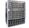
1 About this Guide This guide provides site preparation recommendations and instructions for installing the Dell Force10 C300 chassis, fan tray, power supply units (supplies), route processor modules (RPMs), and line cards. The C300 system is packaged with all of the necessary components, including slot blanks for RPMs, power supplies, and line cards. Information Symbols and Warnings The following graphic symbols are used in this document to bring attention to hazards that exist when handling the C300 and its components. Please read these alerts and heed their warnings and cautions. Table 1-1 describes symbols contained in this guide. Table 1-1. Information Symbols Symbol Warning Description Note This symbol informs you of important operational information. Caution This symbol informs you that improper handling and installation could result in equipment damage or loss of data. Warning This symbol signals information about hardware handling that could result in injury. WARNING: The installation of this equipment shall be performed by trained and qualified personnel only. Read this guide before installing and powering up this equipment. This equipment contains two AC- cords. Disconnect both cords before servicing. WARNING: Class 1 laser product. ATTENTION: Produit laser de classe 1 WARNUNG: Laserprodukt der Klasse 1 WARNING: This equipment contains optical transceivers, which comply with the limits of Class 1 laser radiation. Visible and invisible laser radiation may be emitted from the aperture of the optical transceiver ports when no cable is connected. Avoid exposure to laser radiation and do not stare into open apertures. About this Guide | 7
-
 1
1 -
 2
2 -
 3
3 -
 4
4 -
 5
5 -
 6
6 -
 7
7 -
 8
8 -
 9
9 -
 10
10 -
 11
11 -
 12
12 -
13
-
14
-
15
-
16
-
17
-
18
-
19
-
20
-
21
-
22
-
23
-
24
-
25
-
26
-
27
-
28
-
29
-
30
-
31
-
32
-
33
-
34
-
35
-
36
-
37
-
38
-
39
-
40
-
41
-
42
-
43
-
44
-
45
-
46
-
47
-
48
-
49
-
50
-
51
-
52
-
53
-
54
-
55
-
56
-
57
-
58
-
59
-
60
-
61
-
62
-
63
-
64
-
65
-
66
-
67
-
68
-
69
-
70
-
71
-
72
-
73
-
74
 |
 |
