Dell Inspiron 14 M4010 Inspiron 14 AMD M4010 Service Manual - Page 11
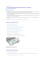
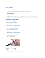
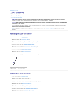
Replacing the Camera Module
 |
View all Dell Inspiron 14 M4010 manuals
Add to My Manuals
Save this manual to your list of manuals |
Page 11 highlights
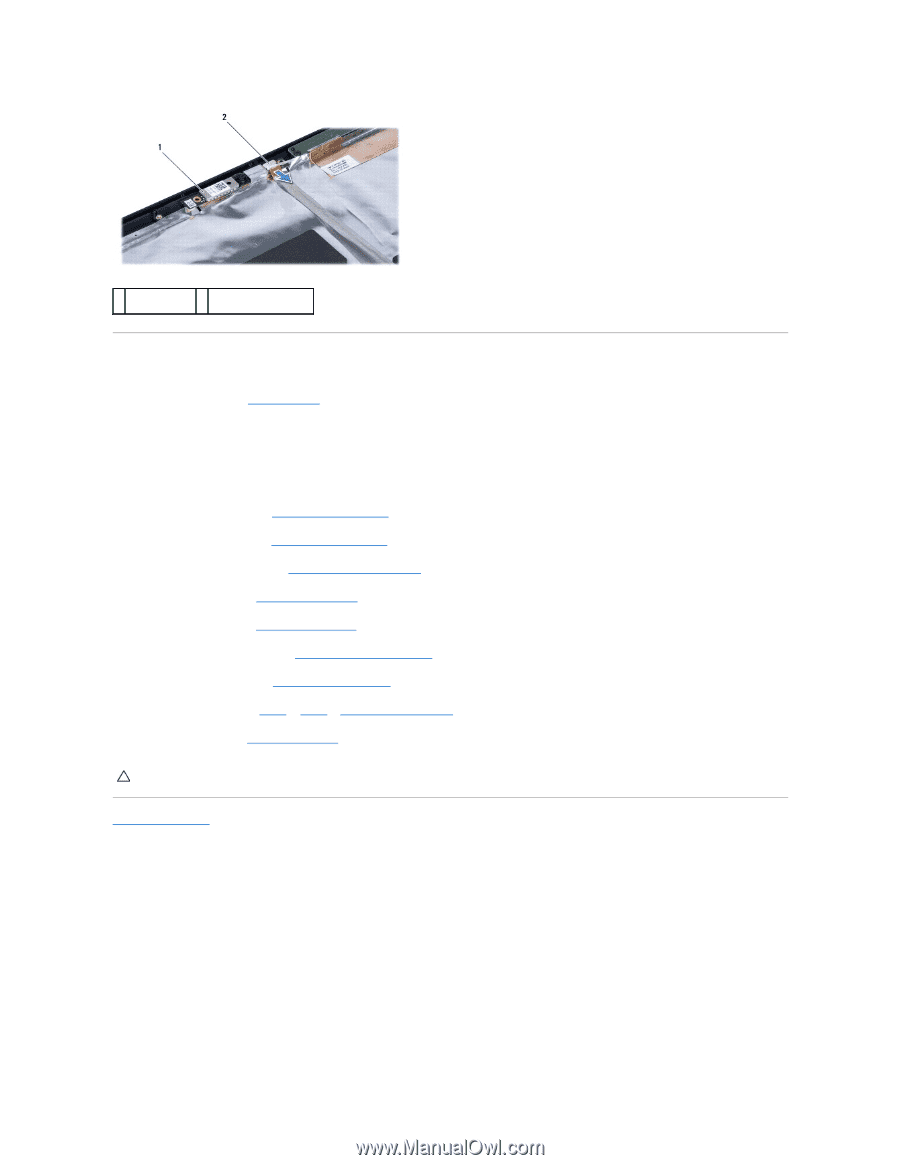
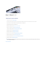
1 camera module 2 camera cable connector Replacing the Camera Module 1. Follow the instructions in Before You Begin. 2. Connect the camera cable to the connector on the camera module. Replace the tape to secure the camera cable to the camera module. 3. Align the slots on the camera module with the alignment guides on the display cover. 4. Adhere the camera module on the display cover. 5. Replace the display panel (see Replacing the Display Panel). 6. Replace the display bezel (see Replacing the Display Bezel). 7. Replace the display assembly (see Replacing the Display Assembly). 8. Replace the palm rest (see Replacing the Palm Rest). 9. Replace the keyboard (see Replacing the Keyboard). 10. Replace the memory module(s) (see Replacing the Memory Module(s)). 11. Replace the module cover (see Replacing the Module Cover). 12. Follow the instructions from step 4 to step 5 in Replacing the Optical Drive. 13. Replace the battery (see Replacing the Battery). CAUTION: Before turning on the computer, replace all screws and ensure that no stray screws remain inside the computer. Failure to do so may result in damage to the computer. Back to Contents Page
-
 1
1 -
2
-
3
-
4
-
5
-
 6
6 -
 7
7 -
 8
8 -
 9
9 -
 10
10 -
 11
11 -
 12
12 -
 13
13 -
 14
14 -
 15
15 -
 16
16 -
17
-
18
-
19
-
20
-
21
-
22
-
23
-
24
-
25
-
26
-
27
-
28
-
29
-
30
-
31
-
32
-
33
-
34
-
35
-
36
-
37
-
38
-
39
-
40
-
41
-
42
-
43
-
44
-
45
-
46
-
47
-
48
-
49
-
50
-
51
-
52
-
53
 |
 |