Dell Inspiron 14 M4010 Inspiron 14 AMD M4010 Service Manual - Page 40
Replacing the Mini-Cards
 |
View all Dell Inspiron 14 M4010 manuals
Add to My Manuals
Save this manual to your list of manuals |
Page 40 highlights
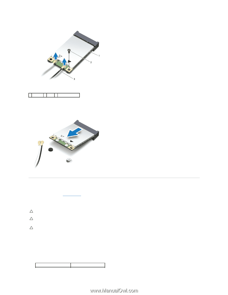
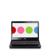
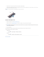
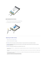
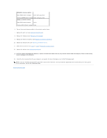
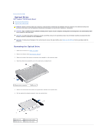
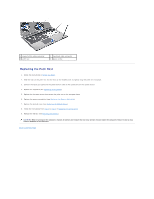
1 Mini-Card 2 screw 3 antenna cables (2) 9. Remove the screw that secures the Mini-Card to the daughter board. 10. Lift the Mini-Card out of the connector on the daughter board. Replacing the Mini-Card(s) 1. Follow the instructions in Before You Begin. 2. Remove the new Mini-Card from its packaging. CAUTION: Use firm and even pressure to slide the card into place. If you use excessive force, you may damage the connector. CAUTION: The connectors are keyed to ensure correct insertion. If you feel resistance, check the connectors on the card and on the system board, and realign the card. CAUTION: To avoid damage to the Mini-Card, never place cables under the card. 3. Insert the Mini-Card connector at a 45-degree angle into the appropriate daughter board connector. For example, the WLAN card connector is labeled WLAN and so on. 4. Press the other end of the Mini-Card down into the slot on the daughter board and replace the screw that secures the Mini-Card to the daughter board connector. 5. Connect the appropriate antenna cables to the Mini-Card you are installing. The following table provides the antenna cable color scheme for each MiniCard supported by your computer. Connectors on the Mini-Card Antenna Cable Color Scheme
-
 1
1 -
2
-
3
-
4
-
5
-
6
-
7
-
8
-
9
-
10
-
11
-
12
-
13
-
14
-
15
-
16
-
17
-
18
-
19
-
20
-
21
-
22
-
23
-
24
-
25
-
26
-
27
-
28
-
29
-
30
-
31
-
32
-
33
-
34
-
 35
35 -
 36
36 -
 37
37 -
 38
38 -
 39
39 -
 40
40 -
 41
41 -
 42
42 -
 43
43 -
 44
44 -
 45
45 -
46
-
47
-
48
-
49
-
50
-
51
-
52
-
53
 |
 |