Dell Inspiron 14 M4010 Inspiron 14 AMD M4010 Service Manual - Page 24
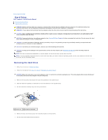
Display Hinges
 |
View all Dell Inspiron 14 M4010 manuals
Add to My Manuals
Save this manual to your list of manuals |
Page 24 highlights
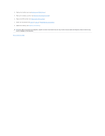
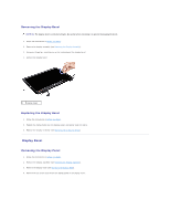
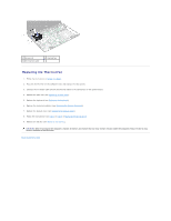
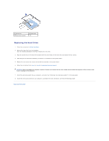
2. Replace the six screws (three on each side) that secure the display panel brackets to the display panel. 3. Connect the display cable to the display board connector and secure it with the tape. 4. Align the screw holes on the display panel with the screw holes on the display cover and replace the six screws. 5. Replace the display bezel (see Replacing the Display Bezel). 6. Replace the display assembly (see Replacing the Display Assembly). CAUTION: Before turning on the computer, replace all screws and ensure that no stray screws remain inside the computer. Failure to do so may result in damage to the computer. Display Hinges Removing the Display Hinges 1. Follow the instructions in Before You Begin. 2. Remove the display assembly (see Removing the Display Assembly). 3. Remove the display bezel (see Removing the Display Bezel). 4. Remove the display panel (see Removing the Display Panel). 5. Remove the two screws (one on each side) that secure the display hinges to the display cover and remove the display hinges. 1 display hinges (2) 2 screws (2) 6. Remove the hinge caps (see Removing the Hinge Caps). Replacing the Display Hinges 1. Follow the instructions in Before You Begin. 2. Replace the hinge caps (see Replacing the Hinge Caps). 3. Route the Mini-Card antenna cables on the display hinge. 4. Align the screw hole on the display hinges with the screw hole on the display cover and replace the two screws (one on each side). 5. Replace the display panel (see Replacing the Display Panel). 6. Replace the display bezel (see Replacing the Display Bezel). 7. Replace the display assembly (see Replacing the Display Assembly).
-
 1
1 -
2
-
3
-
4
-
5
-
6
-
7
-
8
-
9
-
10
-
11
-
12
-
13
-
14
-
15
-
16
-
17
-
18
-
 19
19 -
 20
20 -
 21
21 -
 22
22 -
 23
23 -
 24
24 -
 25
25 -
 26
26 -
 27
27 -
 28
28 -
 29
29 -
30
-
31
-
32
-
33
-
34
-
35
-
36
-
37
-
38
-
39
-
40
-
41
-
42
-
43
-
44
-
45
-
46
-
47
-
48
-
49
-
50
-
51
-
52
-
53
 |
 |