Dell Inspiron 16 Plus 7630 Owners Manual- NVIDIA GeForce RTX 4060 - Page 77
Connect the keyboard-backlight cable to system board and close the latch.
 |
View all Dell Inspiron 16 Plus 7630 manuals
Add to My Manuals
Save this manual to your list of manuals |
Page 77 highlights
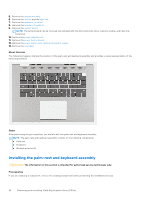
Steps 1. Connect the power-adapter port cable to its connector the system board. 2. Adhere the tape that secures the power-adapter port to its connector on the system board. 3. Gently turn over the system board and place the system board on the palm-rest and keyboard assembly. 4. Align the screw holes on the system board with the screw holes on the palm-rest and keyboard assembly. 5. Replace the four screws (M2x3) that secure the system board to the palm-rest and keyboard assembly. 6. Connect the power-button board cable to its connector on the system board and close the latch. 7. Connect the optional fingerprint-reader cable to its connector on the system board and close the latch. 8. Connect the speaker (woofer) cable to its connector on the system board. 9. Connect the touchpad cable to system board and close the latch. 10. Connect the speaker (tweeter) cable to its connector on the system board. 11. Connect the display-assembly cable to its connector on the system board and close the latch. 12. Adhere the tape that secures the display-assembly cable latch to its connector on the system board. 13. Connect the keyboard cable to its connector on the system board and close the latch. 14. Connect the keyboard-backlight cable to system board and close the latch. 15. Align the screw holes of the Type-C port-bracket with the screw holes of the system board. 16. Place the Type-C port-bracket on the system board. 17. Replace the two screws (M2x5) that secure the Type-C port-bracket to its connector on the system board. Next steps 1. Install the right fan. 2. Install the left fan. 3. Install the heat sink. 4. Install the wireless card. 5. Install the M.2 2230 solid-state drive or M.2 2280 solid-state drive, whichever applicable. 6. Install the memory module. 7. Install the base cover. 8. Follow the procedure in After working inside your computer. Removing and installing Field Replaceable Units (FRUs) 77
-
 1
1 -
2
-
3
-
4
-
5
-
6
-
7
-
8
-
9
-
10
-
11
-
12
-
13
-
14
-
15
-
16
-
17
-
18
-
19
-
20
-
21
-
22
-
23
-
24
-
25
-
26
-
27
-
28
-
29
-
30
-
31
-
32
-
33
-
34
-
35
-
36
-
37
-
38
-
39
-
40
-
41
-
42
-
43
-
44
-
45
-
46
-
47
-
48
-
49
-
50
-
51
-
52
-
53
-
54
-
55
-
56
-
57
-
58
-
59
-
60
-
61
-
62
-
63
-
64
-
65
-
66
-
67
-
68
-
69
-
70
-
71
-
 72
72 -
 73
73 -
 74
74 -
 75
75 -
 76
76 -
 77
77 -
 78
78 -
 79
79 -
 80
80 -
 81
81 -
 82
82 -
83
-
84
-
85
-
86
-
87
-
88
-
89
-
90
-
91
-
92
-
93
-
94
-
95
-
96
-
97
-
98
-
99
-
100
-
101
 |
 |
