Dell Inspiron 16 Plus 7630 Owners Manual- NVIDIA GeForce RTX 4060 - Page 79
Touchpad, Removing the touchpad
 |
View all Dell Inspiron 16 Plus 7630 manuals
Add to My Manuals
Save this manual to your list of manuals |
Page 79 highlights
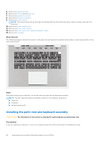
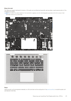
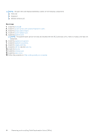
About this task The following image(s) indicate the location of the power-adapter port and provides a visual representation of the installation procedure. Steps 1. Place the power-adapter port into the slot on the palm-rest and keyboard assembly. 2. Adhere the tape that secures the power-adapter cable to the palm-rest and keyboard assembly. 3. Close the right display-assembly hinge. 4. Align the screw holes on the right display-assembly hinge with the screw holes on the system board. 5. Replace the two screws (M2.5x5.5) that secure the right display-assembly hinge to the system board. Next steps 1. Install the system board. NOTE: The system board can be removed and installed with the M.2 solid-state drive, memory module, and heat sink attached. 2. Install the base cover. 3. Follow the procedure in After working inside your computer. Touchpad Removing the touchpad CAUTION: The information in this section is intended for authorized service technicians only. Prerequisites 1. Follow the procedure in Before working inside your computer. NOTE: Ensure that your computer is in Service Mode. For more information see, step 6 in Before working inside your computer. 2. Remove the base cover. 3. Remove the battery. Removing and installing Field Replaceable Units (FRUs) 79
-
 1
1 -
2
-
3
-
4
-
5
-
6
-
7
-
8
-
9
-
10
-
11
-
12
-
13
-
14
-
15
-
16
-
17
-
18
-
19
-
20
-
21
-
22
-
23
-
24
-
25
-
26
-
27
-
28
-
29
-
30
-
31
-
32
-
33
-
34
-
35
-
36
-
37
-
38
-
39
-
40
-
41
-
42
-
43
-
44
-
45
-
46
-
47
-
48
-
49
-
50
-
51
-
52
-
53
-
54
-
55
-
56
-
57
-
58
-
59
-
60
-
61
-
62
-
63
-
64
-
65
-
66
-
67
-
68
-
69
-
70
-
71
-
72
-
73
-
 74
74 -
 75
75 -
 76
76 -
 77
77 -
 78
78 -
 79
79 -
 80
80 -
 81
81 -
 82
82 -
 83
83 -
 84
84 -
85
-
86
-
87
-
88
-
89
-
90
-
91
-
92
-
93
-
94
-
95
-
96
-
97
-
98
-
99
-
100
-
101
 |
 |
