Dell Inspiron X200 Service Manual
Dell Inspiron X200 Manual
 |
View all Dell Inspiron X200 manuals
Add to My Manuals
Save this manual to your list of manuals |
Dell Inspiron X200 manual content summary:
- Dell Inspiron X200 | Service Manual - Page 1
Dell™ X200 Service Manual Before You Begin Preparing to Work Inside the Computer Recommended Tools Computer Orientation Screw Identification System Components Battery Memory Module and Mini PCI Card Memory Module Mini PCI Card Keyboard Palm Rest Hard Drive Hinge Covers and Display Assembly Hinge - Dell Inspiron X200 | Service Manual - Page 2
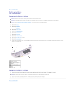
Back to Contents Page Battery Latches Dell™ X200 Service Manual Removing the Battery Latches NOTICE: Disconnect Remove the display assembly. 6. Remove the keyboard tray. 7. Remove the hard drive. 8. Remove the memory module. 9. Remove the Mini PCI card, if present. 10. Remove the system board. 11. - Dell Inspiron X200 | Service Manual - Page 3
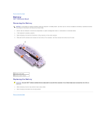
Back to Contents Page Battery Dell™ X200 Service Manual Removing the Battery NOTICE: If you choose to replace the battery with the computer in standby mode, you have up to 1 minute to complete the battery replacement before the computer shuts down and loses any unsaved data. 1. Ensure that the - Dell Inspiron X200 | Service Manual - Page 4
Before You Begin Dell™ X200 Service Manual Preparing to Work Inside the Computer Recommended Tools Computer Orientation Screw Identification Preparing to Work Inside the Computer CAUTION: Before working inside your computer, read the safety instructions in your System Information Guide. NOTICE: Only - Dell Inspiron X200 | Service Manual - Page 5
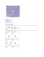
1 back 2 right 3 front 4 left Screw Identification When you are removing and replacing components, photocopy the placemat as a tool to lay out and keep track of the screws. The placemat provides the number of screws and their sizes. NOTICE: When reinstalling a screw, you must use a screw of - Dell Inspiron X200 | Service Manual - Page 6
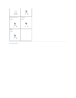
Modem Daughter Card: (1 each) Cooling Fan: (4 each) Speaker: (1 each) Back to Contents Page - Dell Inspiron X200 | Service Manual - Page 7
Back to Contents Page Flashing the BIOS Dell™ X200 Service Manual To update the basic input/output system (BIOS): 1. Go to support.dell.com. If this is your first time to use the website, complete the one-time registration. 2. Enter the service tag sequence for your computer or select the - Dell Inspiron X200 | Service Manual - Page 8
Back to Contents Page Hinge Covers and Display Assembly Dell™ X200 Service Manual Hinge Covers Display Assembly Hinge Covers Removing the Hinge Covers 1. Remove the battery. 2. On the inside of the battery bay, use your fingers to unhook the hinge covers from the back of the computer. 1 hinge covers - Dell Inspiron X200 | Service Manual - Page 9
1 M2 x 6-mm screws (2) 4. Turn the computer over, and remove the two M3 x 5-mm screws from the bottom of the computer. 1 M3 x 5-mm screws (2) 5. Turn the computer over, and open the display 180 degrees. 6. Disconnect the antenna connector. NOTICE: Do not pull on the signal cable and inverter cable. - Dell Inspiron X200 | Service Manual - Page 10
1 signal cable 2 inverter cable 3 inverter connector 4 signal connector 9. Move the display assembly to an upright position and pull it up out of the bottom case. Back to Contents Page - Dell Inspiron X200 | Service Manual - Page 11
Back to Contents Page Cooling Fan Dell™ X200 Service Manual Removing the Cooling Fan NOTICE: Disconnect the Read "Preparing to Work Inside the Computer" before performing the following procedure. 1. Remove the battery. 2. Remove the keyboard. 3. Remove the palm rest. 4. Remove the hinge covers. - Dell Inspiron X200 | Service Manual - Page 12
Back to Contents Page Hard Drive Dell™ X200 Service Manual Removing the Hard Drive NOTICE: Disconnect the computer Read "Preparing to Work Inside the Computer" before performing the following procedure. 1. Remove the battery. 2. Remove the keyboard. 3. Remove the palm rest. 4. Loosen the three M2 x - Dell Inspiron X200 | Service Manual - Page 13
Back to Contents Page Keyboard Dell™ X200 Service Manual Removing the Keyboard NOTICE: Disconnect the computer and : Read "Preparing to Work Inside the Computer" before performing the following procedure. 1. Remove the battery. 2. Remove the six M2 x 4-mm screws labeled with an arrow (one of the six - Dell Inspiron X200 | Service Manual - Page 14
1 keyboard locator tab 2 keyboard securing tabs (4) 4. Pry up the keyboard locator tab, and the keyboard pops up. 5. Pull the keyboard a small distance toward the front of the computer to release the four securing tabs located across the back edge of the keyboard. 6. Rotate the keyboard toward the - Dell Inspiron X200 | Service Manual - Page 15
and hold the cable steady while you close the ZIF connector. (The blue line may reappear after the connector is closed, which should not indicate a problem with the connection.) NOTICE: Position the keyboard flex cable so that it is not pinched when you replace the keyboard in the bottom case - Dell Inspiron X200 | Service Manual - Page 16
Back to Contents Page Keyboard Tray Dell™ X200 Service Manual Removing the Keyboard Tray NOTICE: Disconnect the Read "Preparing to Work Inside the Computer" before performing the following procedure. 1. Remove the battery. 2. Remove the keyboard. 3. Remove the palm rest. 4. Remove the hinge covers. - Dell Inspiron X200 | Service Manual - Page 17
1 air vent 2 pin holes (2) 2. Replace the keyboard tray. 3. Reinstall the seven M2 x 4-mm screws that secure the keyboard tray to the system board. Back to Contents Page - Dell Inspiron X200 | Service Manual - Page 18
Back to Contents Page Modem Daughter Card Dell™ X200 Service Manual Removing the Modem Daughter Card NOTICE: "Preparing to Work Inside the Computer" before performing the following procedure. 1. Remove the battery. 2. Remove the keyboard. 3. Remove the palm rest. 4. Remove the hinge covers. - Dell Inspiron X200 | Service Manual - Page 19
- Dell Inspiron X200 | Service Manual - Page 20
to Contents Page Palm Rest Dell™ X200 Service Manual Removing the Palm Rest "Preparing to Work Inside the Computer" before performing the following procedure. 1. Remove the battery. 2. Remove the keyboard. 3. Turn the computer over, and remove the four M2 not indicate a problem with the connection.) - Dell Inspiron X200 | Service Manual - Page 21
Back to Contents Page - Dell Inspiron X200 | Service Manual - Page 22
Back to Contents Page Pin Assignments for I/O Connectors Dell™ X200 Service Manual Pin Assignments for the Computer Pin Assignments for the X200 MediaBase Pin Assignments for the Computer USB Connector Pin Signal 1 VCC 2 -Data 3 +Data 4 Ground Video Connector Pin Signal 1 RED 2 - Dell Inspiron X200 | Service Manual - Page 23
2 TPB- 3 P12V 4 GND 5 TPB+ 6 TPA+ Pin Assignments for the X200 MediaBase Docking Connector Pin Signal 1 DCK3_DOCK_IN2 2 KBC3_DCKRST 3 ADID 4 DCK_DCIN 5 PIO3_STROBE 6 VGA3_RED 7 PIO3_ACK 8 VGA3_GREEN 9 PIO3_BUSY 10 VGA3_BLUE 11 PIO3_PE 12 VGA5_DDCD 13 NC 14 VGA5_DDCC 15 - Dell Inspiron X200 | Service Manual - Page 24
39 PIO3_PD(6) 40 FDD3_TRK0 41 PIO3_PD(7) 42 FDD3_RDATA 43 NC 44 NC 45 LAN3_EECLK 46 FDD3_J3MODE 47 LAN3_DTOEE 48 FDD3_DS0 49 LAN3_DFRMEE 50 FDD3_MTR0 89 USB3_P590 LAN3_RX91 NC 92 NC 93 USB3_P4+ 94 LAN3_TX+ 95 USB3_P496 LAN3_TX97 NC 98 NC 99 KBC3_DCKPWRON 100 DCK3_DOCK_IN1 PS/2 Connector Pin - Dell Inspiron X200 | Service Manual - Page 25
3 TPA- 4 TPA- Serial Connector Pin Signal Pin 1 DCD 6 2 RXDA 7 3 TXDA 8 4 DTR 9 5 GND Parallel Connector Signal DSR RTS CTS RI Pin Signal 1 STRB#/5V 2 PD0/INDEX# 3 PD1/TRK0# 4 PD2/WP# 5 PD3/RDATA# 6 PD4/DSKCHG# 7 PD5F 8 PD6F 9 PD7F Pin 10 11 12 13 14 15 16 - Dell Inspiron X200 | Service Manual - Page 26
7 GND 8 GND 15 CLK_DDC2 Back to Contents Page - Dell Inspiron X200 | Service Manual - Page 27
Page Reserve Battery Dell™ X200 Service Manual Removing the Reserve Battery NOTICE: Battery 1. Connect the reserve battery connector to the system board connector. 2. Press the reserve battery into place on the bottom case. 3. Update the BIOS using a flash BIOS update program. For instructions - Dell Inspiron X200 | Service Manual - Page 28
Back to Contents Page Speakers Dell™ X200 Service Manual Removing the Speakers NOTICE: Disconnect the computer and : Read "Preparing to Work Inside the Computer" before performing the following procedure. 1. Remove the battery. 2. Remove the keyboard. 3. Remove the palm rest. 4. Remove the M2 x 4-mm - Dell Inspiron X200 | Service Manual - Page 29
Board Dell™ X200 Service Manual Remove the keyboard tray. 7. Remove the hard drive. 8. Remove the memory module. 9. Remove the Mini PCI card, if present. 10. Remove from their system board connectors. 12. Disconnect the reserve battery connector from the system board connector. 13. Lift the - Dell Inspiron X200 | Service Manual - Page 30
connector. 4. Reinstall the four M2 x 4-mm screws that secure the system board to the bottom case. NOTE: After replacing the system board, enter the computer service tag sequence into the BIOS of the replacement system board. Back to Contents Page - Dell Inspiron X200 | Service Manual - Page 31
Page System Components Dell™ X200 Service Manual NOTICE: Only a certified service technician should perform repairs on your computer. Damage due to servicing that is not authorized by Dell is not covered by your warranty. NOTICE: Unless otherwise noted, each procedure in this manual assumes that - Dell Inspiron X200 | Service Manual - Page 32
Back to Contents Page Memory Module and Mini PCI Card Dell™ X200 Service Manual Memory Module Mini PCI Card Memory Module Removing the Memory Module Cover NOTICE: Disconnect the computer and any attached devices from electrical outlets, and remove any installed batteries. NOTICE: To avoid ESD, - Dell Inspiron X200 | Service Manual - Page 33
difficult to close, remove the module and reinstall it. Forcing the cover to close may damage your computer. 1 captive screw 2 memory module cover 3. Insert the battery into the battery bay, or connect the AC adapter to your computer and an electrical outlet. 4. Turn on the computer. As the computer - Dell Inspiron X200 | Service Manual - Page 34
1 captive screw 2 Mini PCI card cover Removing the Mini PCI Card 1. Disconnect the antenna cable from the Mini PCI card. 2. Release the Mini PCI card by spreading the metal securing tabs until the card pops up slightly. 3. Lift the Mini PCI card out of its connector. Replacing the Mini PCI Card 1.
-
 1
1 -
 2
2 -
 3
3 -
 4
4 -
 5
5 -
 6
6 -
 7
7 -
8
-
9
-
10
-
11
-
12
-
13
-
14
-
15
-
16
-
17
-
18
-
19
-
20
-
21
-
22
-
23
-
24
-
25
-
26
-
27
-
28
-
29
-
30
-
31
-
32
-
33
-
34
 |
 |

Dell™ X200 Service Manual
Before You Begin
Preparing to Work Inside the Computer
Recommended Tools
Computer Orientation
Screw Identification
System Components
Battery
Memory Module and Mini PCI Card
Memory Module
Mini PCI Card
Keyboard
Palm Rest
Hard Drive
Hinge Covers and Display Assembly
Hinge Covers
Display Assembly
Keyboard Tray
Reserve Battery
Speakers
Cooling Fan
System Board
Modem Daughter Card
Battery Latches
Flashing the BIOS
Pin Assignments for I/O Connectors
Pin Assignments for the Computer
Pin Assignments for the X200 MediaBase
Notes, Notices, and Cautions
Information in this document is subject to change without notice.
© 2002 Dell Computer Corporation. All rights reserved.
Reproduction in any manner whatsoever without the written permission of Dell Computer Corporation
is strictly forbidden.
Trademarks used in this text:
Dell
, the
DELL
logo, and
AccessDirect
are trademarks of Dell Computer Corporation.
Other trademarks and trade names may be used in this document to refer to either the entities claiming the marks and names or their products. Dell Computer Corporation
disclaims any proprietary interest in trademarks and trade names other than its own.
August 2002 Rev. A00
NOTE:
A NOTE indicates important information that helps you make better use of your computer.
NOTICE:
A NOTICE indicates either potential damage to hardware or loss of data and tells you how to avoid the problem.
CAUTION:
A CAUTION indicates a potential for property damage, personal injury, or death.