Dell Inspiron X200 Service Manual - Page 22
Pin Assignments for I/O Connectors
 |
View all Dell Inspiron X200 manuals
Add to My Manuals
Save this manual to your list of manuals |
Page 22 highlights
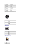
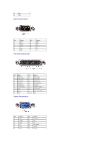
Back to Contents Page Pin Assignments for I/O Connectors Dell™ X200 Service Manual Pin Assignments for the Computer Pin Assignments for the X200 MediaBase Pin Assignments for the Computer USB Connector Pin Signal 1 VCC 2 -Data 3 +Data 4 Ground Video Connector Pin Signal 1 RED 2 GREEN 3 BLUE 4 NC 5 GND 6 GND 7 GND 8 GND Pin Signal 9 CRT_VCC 10 GND 11 NC 12 DAT_DDC2 13 HSYNC 14 VSYNC 15 CLK_DDC2 IEEE 1394 Connector 1 TPA-
-
 1
1 -
2
-
3
-
4
-
5
-
6
-
7
-
8
-
9
-
10
-
11
-
12
-
13
-
14
-
15
-
16
-
 17
17 -
 18
18 -
 19
19 -
 20
20 -
 21
21 -
 22
22 -
 23
23 -
 24
24 -
 25
25 -
 26
26 -
 27
27 -
28
-
29
-
30
-
31
-
32
-
33
-
34
 |
 |

Back to Contents Page
Pin Assignments for I/O Connectors
Dell™ X200 Service Manual
Pin Assignments for the Computer
Pin Assignments for the X200 MediaBase
Pin Assignments for the Computer
USB Connector
Video Connector
IEEE 1394 Connector
Pin
Signal
1
VCC
2
-Data
3
+Data
4
Ground
Pin
Signal
Pin
Signal
1
RED
9
CRT_VCC
2
GREEN
10
GND
3
BLUE
11
NC
4
NC
12
DAT_DDC2
5
GND
13
HSYNC
6
GND
14
VSYNC
7
GND
15
CLK_DDC2
8
GND
1
TPA-