Dell Inspiron X200 Service Manual - Page 9
M2 x 6-mm screws 2
 |
View all Dell Inspiron X200 manuals
Add to My Manuals
Save this manual to your list of manuals |
Page 9 highlights
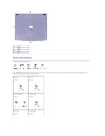
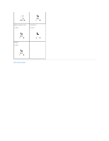
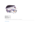
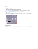
1 M2 x 6-mm screws (2) 4. Turn the computer over, and remove the two M3 x 5-mm screws from the bottom of the computer. 1 M3 x 5-mm screws (2) 5. Turn the computer over, and open the display 180 degrees. 6. Disconnect the antenna connector. NOTICE: Do not pull on the signal cable and inverter cable. Pull from the signal connector and inverter connector to disconnect the cables. 7. Disconnect the signal cable from the system board. 8. Remove the tape that secures the inverter connector, and then disconnect the inverter cable from the system board.
-
 1
1 -
2
-
3
-
 4
4 -
 5
5 -
 6
6 -
 7
7 -
 8
8 -
 9
9 -
 10
10 -
 11
11 -
 12
12 -
 13
13 -
 14
14 -
15
-
16
-
17
-
18
-
19
-
20
-
21
-
22
-
23
-
24
-
25
-
26
-
27
-
28
-
29
-
30
-
31
-
32
-
33
-
34
 |
 |

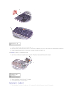
4.
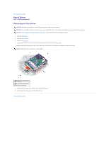
Turn the computer over, and remove the two M3 x 5-mm screws from the bottom of the computer.
5.
Turn the computer over, and open the display 180 degrees.
6.
Disconnect the antenna connector.
7.
Disconnect the signal cable from the system board.
8.
Remove the tape that secures the inverter connector, and then disconnect the inverter cable from the system board.
1
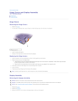
M2 x 6-mm screws (2)
1
M3 x 5-mm screws (2)
NOTICE:
Do not pull on the signal cable and inverter cable. Pull from the signal connector and inverter connector to disconnect the cables.