Dell Inspiron X200 Service Manual - Page 29
System Board
 |
View all Dell Inspiron X200 manuals
Add to My Manuals
Save this manual to your list of manuals |
Page 29 highlights
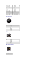
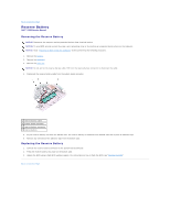
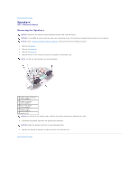
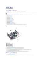
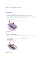
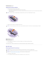
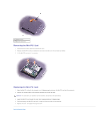
Back to Contents Page System Board Dell™ X200 Service Manual Removing the System Board NOTICE: Disconnect the computer and any attached devices from electrical outlets. NOTICE: To avoid ESD, ground yourself by using a wrist grounding strap or by touching an unpainted metal surface on the computer. NOTICE: Read "Preparing to Work Inside the Computer" before performing the following procedure. 1. Remove the battery. 2. Remove the keyboard. 3. Remove the palm rest. 4. Remove the hinge covers. 5. Remove the display assembly. 6. Remove the keyboard tray. 7. Remove the hard drive. 8. Remove the memory module. 9. Remove the Mini PCI card, if present. 10. Remove the four M2 x 4-mm screws that secure the system board to the bottom case. NOTE: Each system board screw has an arrow beside it. 1 system board 2 M2 x 4-mm screws (4) 3 status light (LED) cable 4 ZIF connector 11. Disconnect the left and right speakers from their system board connectors. 12. Disconnect the reserve battery connector from the system board connector. 13. Lift the ZIF connector, and remove the status light (LED) cable from its ZIF connector on the system board. 14. Lift the system board up and out of the bottom case. 15. Remove the modem daughter card, and set it aside to install in the replacement system board. Replacing the System Board 1. Install the modem daughter card that you removed from the old system board in the replacement system board. 2. Place the system board in the bottom case.
-
 1
1 -
2
-
3
-
4
-
5
-
6
-
7
-
8
-
9
-
10
-
11
-
12
-
13
-
14
-
15
-
16
-
17
-
18
-
19
-
20
-
21
-
22
-
23
-
 24
24 -
 25
25 -
 26
26 -
 27
27 -
 28
28 -
 29
29 -
 30
30 -
 31
31 -
 32
32 -
 33
33 -
 34
34
 |
 |