Dell Inspiron X200 Service Manual - Page 30
After replacing the system board, enter the computer service tag sequence into the BIOS of
 |
View all Dell Inspiron X200 manuals
Add to My Manuals
Save this manual to your list of manuals |
Page 30 highlights
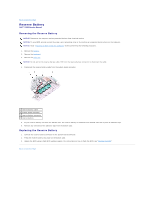
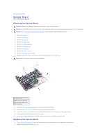
NOTE: Route cables so that they will not be crimped or pinched when the complete assembly is put back together. 3. Reconnect the status light (LED) cable to the system board ZIF connector. 4. Reinstall the four M2 x 4-mm screws that secure the system board to the bottom case. NOTE: After replacing the system board, enter the computer service tag sequence into the BIOS of the replacement system board. Back to Contents Page
-
 1
1 -
2
-
3
-
4
-
5
-
6
-
7
-
8
-
9
-
10
-
11
-
12
-
13
-
14
-
15
-
16
-
17
-
18
-
19
-
20
-
21
-
22
-
23
-
24
-
 25
25 -
 26
26 -
 27
27 -
 28
28 -
 29
29 -
 30
30 -
 31
31 -
 32
32 -
 33
33 -
 34
34
 |
 |

3.
Reconnect the status light (LED) cable to the system board ZIF connector.
4.
Reinstall the four M2 x 4-mm screws that secure the system board to the bottom case.
Back to Contents Page
NOTE:
Route cables so that they will not be crimped or pinched when the complete assembly is put back together.
NOTE:
After replacing the system board, enter the computer service tag sequence into the BIOS of the replacement system board.