Dell Latitude 5404 Dell Latitude 14 Rugged 5404Series Owners Manual - Page 20
Installing the RF Holder, Removing the Heatsink, Before Working Inside Your Computer
 |
View all Dell Latitude 5404 manuals
Add to My Manuals
Save this manual to your list of manuals |
Page 20 highlights
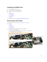
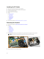
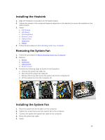
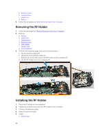
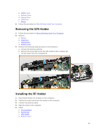
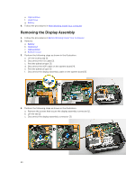
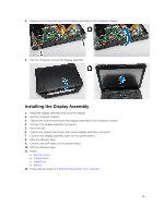
Installing the RF Holder 1. Place the RF holder into its place on the computer. 2. Tighten the screw that secure the holder to the computer. 3. Connect the antenna cable. 4. Align the cable to the computer. 5. Install: a. Docking Board b. WLAN Card c. GPS Holder d. Bottom Cover e. Optical Drive f. Hard Drive g. Battery 6. Follow the procedures in After Working Inside Your computer Removing the Heatsink 1. Follow the procedures in Before Working Inside Your Computer 2. Remove: a. Battery b. Hard Drive c. Optical Drive d. Bottom Cover e. Docking Board f. GPU Board g. SIM Module 3. Loosen the screws that secure the heatsink to the system board in the sequence shown [1,2,3,4]. NOTE: The screws are retained by the heatsink and should not be fully removed. 4. Lift the heatsink from the computer chassis. 20
-
 1
1 -
2
-
3
-
4
-
5
-
6
-
7
-
8
-
9
-
10
-
11
-
12
-
13
-
14
-
 15
15 -
 16
16 -
 17
17 -
 18
18 -
 19
19 -
 20
20 -
 21
21 -
 22
22 -
 23
23 -
 24
24 -
 25
25 -
26
-
27
-
28
-
29
-
30
-
31
-
32
-
33
-
34
-
35
-
36
-
37
-
38
-
39
-
40
-
41
-
42
-
43
-
44
-
45
-
46
-
47
-
48
-
49
-
50
-
51
-
52
-
53
-
54
-
55
-
56
-
57
-
58
 |
 |
