Dell Latitude 5404 Dell Latitude 14 Rugged 5404Series Owners Manual - Page 24
Removing the Display Assembly, Optical Drive, Hard Drive, Battery, After Working Inside Your computer
 |
View all Dell Latitude 5404 manuals
Add to My Manuals
Save this manual to your list of manuals |
Page 24 highlights
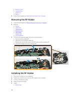
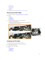
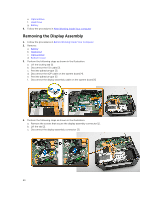
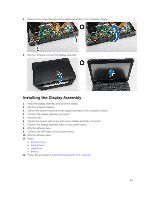
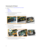
e. Optical Drive f. Hard Drive g. Battery 6. Follow the procedures in After Working Inside Your computer Removing the Display Assembly 1. Follow the procedures in Before Working Inside Your Computer 2. Remove: a. Battery b. Hard Drive c. Optical Drive d. Bottom Cover 3. Perform the following steps as shown in the illustration: a. Lift the locking tab [1]. b. Disconnect the I/O cable [2]. c. Peel the adhesive tape [3]. d. Disconnect the eDP cable on the system board [4]. e. Peel the adhesive tape [5] f. Disconnect the display assembly cable on the system board [6] 4. Perform the following steps as shown in the illustration: a. Remove the screws that secure the display assembly connector [1]. b. Lift the tab [2]. c. Disconnect the display assembly connector [3]. 24
-
 1
1 -
2
-
3
-
4
-
5
-
6
-
7
-
8
-
9
-
10
-
11
-
12
-
13
-
14
-
15
-
16
-
17
-
18
-
 19
19 -
 20
20 -
 21
21 -
 22
22 -
 23
23 -
 24
24 -
 25
25 -
 26
26 -
 27
27 -
 28
28 -
 29
29 -
30
-
31
-
32
-
33
-
34
-
35
-
36
-
37
-
38
-
39
-
40
-
41
-
42
-
43
-
44
-
45
-
46
-
47
-
48
-
49
-
50
-
51
-
52
-
53
-
54
-
55
-
56
-
57
-
58
 |
 |
