Dell OptiPlex 3010 User Manual - Page 60
System Board Connectors - manual
 |
View all Dell OptiPlex 3010 manuals
Add to My Manuals
Save this manual to your list of manuals |
Page 60 highlights
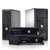
System Board Connectors Mini-Tower, Desktop Small Form Factor Front panel control Processor Processor Fan Mini-Tower, Desktop Small Form Factor Password clear jumper RTC reset jumper Internal speaker Intruder connector Power connector Controls and Lights Front of the computer: Power button light Drive activity light Diagnostic lights Back of the computer: Power supply diagnostic light two 3-pin connector one 5-pin connector one 16-pin, two 10-pin, and one 5-pin connector one 1155-pin connector one 4-pin connector one 5-pin connector one 3-pin connector one 3-pin connector one 5-pin connector one 3-pin connector one 24-pin and one 4-pin connector Blue light - Solid blue light indicates power-on state; blinking blue light indicates sleep state of the computer. Amber light - Solid amber light when the computer does not start indicates a problem with the system board or power supply. Blinking amber light indicates a problem with the system board. Blue light - Blinking blue light indicates that the computer is reading data from or writing data to the hard drive. Four lights located on the front panel of the computer. For more information on the diagnostic lights, see the Service Manual at support.dell.com/manuals. Green light - The power supply is turned on and is functional. The power cable must be connected to the power connector (at the back of the computer) and the electrical outlet. 60
-
 1
1 -
2
-
3
-
4
-
5
-
6
-
7
-
8
-
9
-
10
-
11
-
12
-
13
-
14
-
15
-
16
-
17
-
18
-
19
-
20
-
21
-
22
-
23
-
24
-
25
-
26
-
27
-
28
-
29
-
30
-
31
-
32
-
33
-
34
-
35
-
36
-
37
-
38
-
39
-
40
-
41
-
42
-
43
-
44
-
45
-
46
-
47
-
48
-
49
-
50
-
51
-
52
-
53
-
54
-
 55
55 -
 56
56 -
 57
57 -
 58
58 -
 59
59 -
 60
60 -
 61
61 -
 62
62 -
 63
63
 |
 |