Dell Precision 330 Service Manual
Dell Precision 330 Manual
 |
View all Dell Precision 330 manuals
Add to My Manuals
Save this manual to your list of manuals |
Dell Precision 330 manual content summary:
- Dell Precision 330 | Service Manual - Page 1
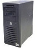
Dell Precision™ WorkStation 330 Systems SERVICE MANUAL www.dell.com support.dell.com - Dell Precision 330 | Service Manual - Page 2
to hardware or loss of data and tells you how to avoid the problem. CAUTION: A CAUTION indicates a potentially hazardous situation which, if not avoided Dell Computer Corporation is strictly forbidden. Trademarks used in this text: Dell Precision and the DELL E COM logo are trademarks of Dell - Dell Precision 330 | Service Manual - Page 3
Precautionary Measures 12 Recommended Tools 12 Restarting the System 13 2 Computer Cover Desktop Chassis 16 Removing the Computer Cover (Desktop Chassis 16 Replacing the Computer Cover (Desktop Chassis 17 Mini Tower Chassis 18 Removing the Computer Cover (Mini Tower Chassis 18 Replacing - Dell Precision 330 | Service Manual - Page 4
Tower Chassis 46 Removing Front-Panel Buttons (Mini Tower Chassis 46 Replacing Front-Panel Buttons (Mini Tower Chassis 47 9 Power Supply Desktop Chassis 50 Rotating the Power Supply (Desktop Chassis 50 Removing the Power Supply (Desktop Chassis 51 Replacing the Power Supply (Desktop Chassis - Dell Precision 330 | Service Manual - Page 5
Mini Tower Chassis 53 Rotating the Power Supply (Mini Tower Chassis 53 Removing the Power Supply (Mini Tower Chassis 54 Replacing the Power Supply (Mini Tower Chassis 55 10 System Memory Removing a Memory Module 58 Replacing a Memory Module 59 11 Disk Drives and Media Desktop Chassis 64 - Dell Precision 330 | Service Manual - Page 6
109 Mini Tower Chassis 109 Removing the Expansion-Card Guide (Mini Tower Chassis) ..........110 Replacing the Expansion-Card Guide (Mini Tower Chassis) ..........111 15 I/O Cooling Fan (Mini Tower Chassis Only) Removing the I/O Cooling Fan 114 Replacing the I/O Cooling Fan 115 16 Control Panel - Dell Precision 330 | Service Manual - Page 7
Hard-Drive Thermal Sensor Desktop Chassis 124 Removing the Hard-Drive Thermal Sensor (Desktop Chassis) .......124 Replacing the Hard-Drive Thermal Sensor (Desktop Chassis) ...... 125 Mini Tower Chassis 126 Removing the Hard-Drive Thermal Sensor (Mini Tower Chassis) ..126 Replacing the Hard-Drive - Dell Precision 330 | Service Manual - Page 8
Microprocessor Cooling Fan (Mini Tower Chassis) .155 Replacing the Microprocessor Cooling Fan (Mini Tower Chassis) .157 23 VRM Overview 160 Removing the VRM 160 Replacing the VRM 161 24 System Battery Removing the System Battery 164 Replacing the System Battery 165 25 System Board 8 Contents - Dell Precision 330 | Service Manual - Page 9
Removing the System Board 168 Replacing the System Board 169 Contents 9 - Dell Precision 330 | Service Manual - Page 10
10 Contents - Dell Precision 330 | Service Manual - Page 11
SECTION 1 Before You Begin Precautionary Measures Recommended Tools Restarting the System www.dell.com | support.dell.com 1 - Dell Precision 330 | Service Manual - Page 12
or on the computer chassis, such as the power supply, to discharge any static charge from your body before power indicator on the system board is not on. If it is on, you may need to wait 10 to 30 seconds for it to go out. To locate this indicator, see "System Board Components" or "Interior Service - Dell Precision 330 | Service Manual - Page 13
Intrusion option will cause the following message to be displayed at the next system start-up: ALERT! Cover was previously removed. 2 To reset the Chassis Intrusion option, enter system setup, select the System Security option, and reset the Chassis Intrusion option to Enabled or Enabled Silent - Dell Precision 330 | Service Manual - Page 14
www.dell.com | support.dell.com 14 Be fo r e Yo u Be g in - Dell Precision 330 | Service Manual - Page 15
SECTION 2 Computer Cover Desktop Chassis Mini Tower Chassis www.dell.com | support.dell.com 2 - Dell Precision 330 | Service Manual - Page 16
www.dell.com | support.dell.com Desktop Chassis • Removing the computer cover • Replacing the computer cover Removing the Computer Cover (Desktop Chassis) CAUTION: Before you perform this procedure, see "Precautionary Measures." 1 Turn off the computer and peripherals, and disconnect them from - Dell Precision 330 | Service Manual - Page 17
Removing the Cover (Desktop Chassis) padlock ring cover release buttons (2) D c Lift the way so that they do not catch on the computer cover. Ensure that cables are not routed over the drive cage-they will prevent the cover from closing properly. 2 Ensure that no tools or extra parts (including - Dell Precision 330 | Service Manual - Page 18
www.dell.com | support.dell.com Replacing the Cover (Desktop Chassis) cover release buttons (2) recessed slots (3) hooks (3) Mini Tower Chassis • Removing the computer cover • Replacing the computer cover Removing the Computer Cover (Mini Tower Chassis) CAUTION: Before you perform this procedure - Dell Precision 330 | Service Manual - Page 19
3 Remove the computer cover. a Face the back of the computer and slide the outer padlock ring to the left to unlock the cover release mechanism (see - Dell Precision 330 | Service Manual - Page 20
www.dell.com | support.dell.com Removing the Cover (Mini Tower Chassis) cover release button d Lift so that they do not catch on the computer cover. Ensure that cables are not routed over the drive cage-they will prevent the cover from closing properly. 2 Ensure that no tools or extra parts ( - Dell Precision 330 | Service Manual - Page 21
a Hold the cover at a slight angle as shown in the following figure. While aligning the top of the cover with the top of the chassis, insert the three hooks on the cover into the three recessed slots on the computer chassis. b Rotate the cover downward toward the bottom of the chassis. With both - Dell Precision 330 | Service Manual - Page 22
www.dell.com | support.dell.com 22 Computer Cover - Dell Precision 330 | Service Manual - Page 23
3 SECTION 3 Interior Service Label Service Label www.dell.com | support.dell.com - Dell Precision 330 | Service Manual - Page 24
www.dell.com | support.dell.com Service Label A service label affixed to the inside of your computer cover indicates the location of system board components and connectors. Desktop Chassis Service Label interior view of top cover service label Mini Tow er Chas sis Se r vic e L a be l interior view - Dell Precision 330 | Service Manual - Page 25
4 SECTION 4 Inside Your Computer Chassis Interior www.dell.com | support.dell.com - Dell Precision 330 | Service Manual - Page 26
www.dell.com | support.dell.com Chassis Interior The following figures show the desktop and mini tower chassis with their covers removed. Desktop Chassis Interior drive interface cable DC power cable power supply externally accessible drive bays hard-drive bracket system board AC power - Dell Precision 330 | Service Manual - Page 27
Mini Towe r Chas sis Int er io r power supply AC power receptacle I/O panel connectors externally accessible drive bays hard-drive bracket expansion-card slots padlock ring security cable slot drive interface cable DC power cable system board NOTE: Before you remove the cover from the mini tower - Dell Precision 330 | Service Manual - Page 28
www.dell.com | support.dell.com 28 In s i d e Yo u r C o m p u te r - Dell Precision 330 | Service Manual - Page 29
SECTION 5 System Board Components Components Labels Jumpers www.dell.com | support.dell.com 5 - Dell Precision 330 | Service Manual - Page 30
reset (RTCRST) jumper password jumper auxiliary hard-drive access indicator connector battery socket 1 2 3 4 5 standby power indicator external speaker I/O fan connector Labels The following table lists the labels for connectors and components on the system board, and briefly describes the - Dell Precision 330 | Service Manual - Page 31
hard-drive access indicator connector Battery socket CD audio input connector Microprocessor power connector Diagnostic indicators Diskette-drive connector Microprocessor fan connector I/O fan port connector PCI expansion-card connector System power connector Password jumper RIMM socket Real- - Dell Precision 330 | Service Manual - Page 32
www.dell.com | support.dell.com System-Board Labels (continued) Connector or Component STR TAPI USB USB2 VRM Label Suspend-to-RAM indicator Telephony connector Port 2 USB connectors (2) Port 1 USB connectors (2) VRM connector Jumpers The following figure shows the location of the jumpers on the - Dell Precision 330 | Service Manual - Page 33
System-Board Jumper Settings Jumper Setting Description PSWD (default) Password features are enabled. Password features are disabled. RTCRST Real-time clock reset. Can be used for troubleshooting. jumpered unjumpered S ystem B oard Component s 33 - Dell Precision 330 | Service Manual - Page 34
www.dell.com | support.dell.com 34 Syst em Board Component s - Dell Precision 330 | Service Manual - Page 35
6 SECTION 6 Front Panel (Mini Tower Chassis Only) Removing the Front Panel Replacing the Front Panel www.dell.com | support.dell.com - Dell Precision 330 | Service Manual - Page 36
www.dell.com | support.dell.com Removing the Front Panel CAUTION: Before you perform this procedure, see "Precautionary Measures." 1 Turn off the computer and peripherals, disconnect them from their electrical outlets, wait at least 5 seconds, and then remove the computer cover. 2 Release the front - Dell Precision 330 | Service Manual - Page 37
from the chassis. Replacing the Front Panel Fit the two front-panel retaining hooks into the recessed slots at the bottom of the chassis. See "Removing the Front Panel (Mini Tower Chassis)." Then rotate the top of the panel toward the chassis until the front-panel latches snap into the tabs - Dell Precision 330 | Service Manual - Page 38
www.dell.com | support.dell.com 38 Fr ont Pane l ( Mini Towe r Chas s is Only ) - Dell Precision 330 | Service Manual - Page 39
SECTION 7 Front-Panel Inserts Desktop Chassis Mini Tower Chassis www.dell.com | support.dell.com 7 - Dell Precision 330 | Service Manual - Page 40
www.dell.com | support.dell.com Desktop Chassis • Removing front-panel inserts • Replacing front-panel inserts Removing Front-Panel and then remove the computer cover. 2 Lay the computer cover upside down, with the front panel facing you. 3 Remove the front-panel insert for the chassis drive bay - Dell Precision 330 | Service Manual - Page 41
, disconnect them from their electrical outlets, wait at least 5 seconds, and then remove the computer cover. 2 Remove the front panel. 3 Hold the front panel with the front facing you. 4 Remove the front-panel insert for the chassis drive bay you want to use. Use your thumbs to press the sides of - Dell Precision 330 | Service Manual - Page 42
www.dell.com | support.dell.com Removing Front-Panel Inserts (Mini Tower Chassis) front panel posts (2) ring tabs (2) front-panel insert Replacing Front-Panel Inserts (Mini Tower Chassis) Position the two ring-tabs over the posts on the inside of the bay opening, and then press the ring tabs over - Dell Precision 330 | Service Manual - Page 43
8 SECTION 8 Front-Panel Buttons Desktop Chassis Mini Tower Chassis www.dell.com | support.dell.com - Dell Precision 330 | Service Manual - Page 44
www.dell.com | support.dell.com Desktop Chassis • Removing front-panel buttons • Replacing front-panel buttons Removing Front-Panel Buttons the back of the cover facing you. 3 Remove the front-panel buttons: • To remove the 3.5-inch diskette-drive eject button, pull gently on the button until its - Dell Precision 330 | Service Manual - Page 45
Removing Front-Panel Buttons (Desktop Chassis) computer cover 3.5-inch diskette-drive eject button power button reset button Replacing Front-Panel Buttons (Desktop Chassis) Replace the front-panel buttons. • To replace the 3.5-inch diskette-drive eject button, rotate the button into the hole in - Dell Precision 330 | Service Manual - Page 46
www.dell.com | support.dell.com Mini Tower Chassis • Removing front-panel buttons • Replacing front-panel buttons Removing Front-Panel Buttons (Mini Tower Chassis) 1 Turn off the computer and peripherals, disconnect them from their electrical outlets, wait at least 5 seconds, and then remove the - Dell Precision 330 | Service Manual - Page 47
Removing Front-Panel Buttons (Mini Tower Chassis) front panel power button reset button Replacing Front-Panel Buttons (Mini Tower Chassis) Replace the front-panel buttons. Fr ont-Panel Butt ons 47 - Dell Precision 330 | Service Manual - Page 48
www.dell.com | support.dell.com • To replace the power button, insert the button into the hole in the front panel of the computer cover so that the button's clips secure it to the cover. • - Dell Precision 330 | Service Manual - Page 49
SECTION 9 Power Supply Desktop Chassis Mini Tower Chassis www.dell.com | support.dell.com 9 - Dell Precision 330 | Service Manual - Page 50
www.dell.com | support.dell.com Desktop Chassis • Rotating the power supply • Removing the power supply • Replacing the power supply Rotating the Power Supply (Desktop Chassis) To access some of the components on the system board, you may need to rotate the system power supply out of the way. - Dell Precision 330 | Service Manual - Page 51
the Power Supply (Desktop Chassis) securing tab power supply AC power cable release latch Removing the Power Supply (Desktop Chassis) 1 Rotate the power supply away from the system board. 2 Disconnect the power supply cables from all drives. 3 Disconnect the power supply cables from the system board - Dell Precision 330 | Service Manual - Page 52
inserts into the chassis slot. See "Removing the Power Supply (Desktop Chassis)." 3 Press the right side of the power supply down until the pivot pin snaps into the chassis slot. 4 Connect the power supply cables to the system board. 5 Connect the power supply cables to all drives. 52 Power Supply - Dell Precision 330 | Service Manual - Page 53
cover and restart the system. Mini Tower Chassis • Rotating the power supply • Removing the power supply • Replacing the power supply Rotating the Power Supply (Mini Tower Chassis) To access some of the components on the system board, you may need to rotate the system power supply out of the way - Dell Precision 330 | Service Manual - Page 54
www.dell.com | support.dell.com Rota ting the Powe r Supply (Mini Tow er Chas sis) power supply AC power cable securing tab release latch Removing the Power Supply (Mini Tower Chassis) 1 Rotate the power supply away from the system board. 2 Disconnect the power supply cables from all drives. 3 - Dell Precision 330 | Service Manual - Page 55
the retention arm pin on the left side of the power supply from the retention arm socket. 7 Disengage the pivot pin on the left rear of the power supply from the chassis socket. Removing the Pow er Supply ( Mini Towe r Chass is) power supply right pivot pin left pivot pin chassis slot chassis - Dell Precision 330 | Service Manual - Page 56
pin on the right rear of the power supply inserts into the chassis slot. See "Removing the Power Supply (Mini Tower Chassis)." 4 Connect the power supply cables to the system board. 5 Connect the power supply cables to all drives. 6 Rotate the power supply back into position until the securing tab - Dell Precision 330 | Service Manual - Page 57
SECTION 10 System Memory Removing a Memory Module Replacing a Memory Module www.dell.com | support.dell.com 10 - Dell Precision 330 | Service Manual - Page 58
dell.com | support.dell.com Removing a Memory Module CAUTION: Before you perform this procedure, see "Precautionary Measures." CAUTION: RIMMs can get very hot during system on its right side. 3 Rotate the power supply away from the system board. 4 Remove the memory modules (RIMMs or CRIMMs): a Press - Dell Precision 330 | Service Manual - Page 59
Removing a Memory Module securing clips (2) Replacing a Memory Module 1 Install the memory module: a Press the securing clips at each end of the socket outward until they snap open (see the following figure). b Align the slots on the bottom of the memory module with the two ridges inside the socket. - Dell Precision 330 | Service Manual - Page 60
support.dell.com Installing a Memory Module securing clips (2) slots (2) 2 Rotate the power supply back into position until the securing tab snaps into the release latch. 3 If you have a mini tower chassis, stand the computer upright. 4 Replace the computer cover and restart the system. The system - Dell Precision 330 | Service Manual - Page 61
8 Run the Dell Diagnostics to verify that the memory modules are operating properly. S ys tem Memor y 61 - Dell Precision 330 | Service Manual - Page 62
www.dell.com | support.dell.com 62 Syst em Memor y - Dell Precision 330 | Service Manual - Page 63
11 SECTION 11 Disk Drives and Media Desktop Chassis Mini Tower Chassis www.dell.com | support.dell.com - Dell Precision 330 | Service Manual - Page 64
.dell.com | support.dell.com Desktop Chassis • Drive locations • Removing the diskette drive • Replacing the diskette drive • Removing a CD, Zip, or other externally accessible drive • Replacing a CD, Zip, or other externally accessible drive • Removing a hard drive • Replacing a hard drive Drive - Dell Precision 330 | Service Manual - Page 65
, wait at least 5 seconds, and then remove the computer cover. 2 Rotate the power supply away from the system board. 3 Disconnect the DC power and interface cables from the back of the drive. 4 Press the green diskette-drive bracket release button and slide the drive assembly out of the chassis (see - Dell Precision 330 | Service Manual - Page 66
www.dell.com | support.dell.com Removing the Diskette-Drive Bracket (Desktop Chassis) drive/bracket assembly bracket release button 5 Remove the mounting screw. 6 Rotate the left side of the diskette drive upward and lift it free from the drive bracket (see the following figure). 66 Disk Dri ves - Dell Precision 330 | Service Manual - Page 67
chassis until the green diskette-drive bracket release button snaps securely into place. See "Removing the Diskette-Drive Bracket (Desktop Chassis)." 3 Connect the interface cable for the drive. To locate this connector, see "System Board Components" or "Interior Service Label." Disk Dri ves and - Dell Precision 330 | Service Manual - Page 68
to provide airflow for the fan and cooling vents. 6 Rotate the power supply back into position until the securing tab snaps into the release latch. 7 Replace the computer cover and restart the system. 8 Run the Dell Diagnostics to verify that the drive is operating properly. Removing a CD, Zip, or - Dell Precision 330 | Service Manual - Page 69
Removing a Drive Bracket (Desktop Chassis) drive/bracket assembly bracket tabs (2) 5 Remove the drive from the bracket. Turn the drive/bracket assembly upside down and remove the four screws that secure the drive to the bracket (see the following figure). Disk Dri ves and Media 69 - Dell Precision 330 | Service Manual - Page 70
www.dell.com | support.dell.com Removing the Drive from the Bracket drive bracket tabs (2) drive bracket screws (4) Replacing a CD, Zip, or Other Externally Accessible Drive (Desktop Chassis) 1 Attach the new drive to the drive bracket. Turn the drive upside down, and fit the bracket on the drive - Dell Precision 330 | Service Manual - Page 71
bracket assembly bracket tabs (2) 3 Connect the interface cable for the drive. See "Attaching Drive Cables (Desktop Chassis)." NOTICE: To avoid possible damage, you must match the colored strip on the interface cable with pin 1 on both the drive and system board connectors. Disk Dri ves and Media 71 - Dell Precision 330 | Service Manual - Page 72
connector DC power cable secondary system board EIDE connector interface connector interface cable 5 Ensure that all cables are firmly connected. Fold cables out of the way to provide airflow for the fan and cooling vents. 6 If the chassis drive bay was previously empty, remove the corresponding - Dell Precision 330 | Service Manual - Page 73
the Dell Diagnostics to test the drive. • For other types of drives, see the drive's documentation for information on testing the drive. 12 If the drive you installed is the primary hard drive, install the operating system on the drive. See the operating system's documentation for instructions. NOTE - Dell Precision 330 | Service Manual - Page 74
.dell.com | support.dell.com 3 Disconnect the DC power and interface cables from the back of the drive. 4 Remove the drive bracket from the chassis. Remove the screw holding the drive bracket in the chassis. Lift the drive bracket up to disengage it from the latch on the externally accessible drive - Dell Precision 330 | Service Manual - Page 75
the left side of the chassis when the bracket is installed in the chassis. 2 Align the screw holes of the drive and bracket, and secure the drive in the bracket using the screws that came with the upgrade kit. See "Removing a Hard Drive from the Bracket (Desktop Chassis)." Disk Dri ves and Media 75 - Dell Precision 330 | Service Manual - Page 76
www.dell.com | support.dell.com 3 Reinstall the hard-drive bracket in the chassis (see the following figure). Insert the bracket into the chassis by inserting the hooks in the slots on the front of - Dell Precision 330 | Service Manual - Page 77
fan and cooling vents. 7 Ensure that the control panel cable is firmly connected to the system board. The control panel contains the hard-drive activity indicator. To locate the control panel system board connector, see "System Board Components" or "Interior Service Label." 8 Rotate the power supply - Dell Precision 330 | Service Manual - Page 78
. 12 Run the Dell Diagnostics to test the drive. 13 If the hard drive you installed is the primary drive, install the operating system on the drive. See the operating system's documentation for instructions. Mini Tower Chassis • Drive locations • Removing the diskette drive • Replacing the diskette - Dell Precision 330 | Service Manual - Page 79
accessible drives hard drives Removing the Diskette Drive (Mini Tower Chassis) CAUTION: Before you perform this procedure, see "Precautionary Measures." NOTICE: Before disconnecting a peripheral from the system or removing a component from the system board, verify that the standby power indicator - Dell Precision 330 | Service Manual - Page 80
www.dell.com | support.dell.com 1 Turn off the computer and peripherals, disconnect them from their electrical outlets, wait at least 5 seconds, and then remove the computer cover. 2 Rotate the power supply away from the system board. 3 Remove the front panel. 4 Disconnect the DC power and - Dell Precision 330 | Service Manual - Page 81
chassis until the green diskette-drive bracket release button snaps securely into place. See "Removing the Diskette-Drive Bracket (Mini Tower Chassis)." 3 Connect the interface cable for the drive. To locate this connector, see "System Board Components" or "Interior Service Label." Disk Dri ves and - Dell Precision 330 | Service Manual - Page 82
to provide airflow for the fan and cooling vents. 6 Rotate the power supply back into position until the securing tab snaps into the release latch. 7 Replace the computer cover and restart the system. 8 Run the Dell Diagnostics to verify that the drive is operating properly. Removing a CD, Zip, or - Dell Precision 330 | Service Manual - Page 83
Removing a Drive Bracket (Mini Tower Chassis) bracket tabs (2) 6 Remove the drive from the bracket. Turn the drive/bracket assembly upside down and remove the four screws that secure the drive to the bracket (see the following figure). Disk Dri ves and Media 83 - Dell Precision 330 | Service Manual - Page 84
.dell.com | support.dell.com Removing the Drive from the Bracket drive bracket tabs (2) drive bracket screws (4) Replacing a CD, Zip, or Other Externally Accessible Drive (Mini Tower Chassis) 1 Attach the new drive to the drive bracket. Turn the drive upside down, and fit the bracket on the drive - Dell Precision 330 | Service Manual - Page 85
Cables (Mini Tower Chassis)." NOTICE: To avoid possible damage, you must match the colored strip on the interface cable with pin 1 on both the drive and system board connectors. a If you are installing an EIDE device, ensure that the interface cable is properly connected to the EIDE connector on the - Dell Precision 330 | Service Manual - Page 86
following figure). Attaching Drive Cables (Mini Tower Chassis) power input connector DC power cable secondary system board EIDE connector interface connector interface cable 5 Ensure that all cables are firmly connected. Fold cables out of the way to provide airflow for the fan and cooling vents - Dell Precision 330 | Service Manual - Page 87
the Dell Diagnostics to test the drive. • For other types of drives, see the drive's documentation for information on testing the drive. 13 If the drive you installed is the primary hard drive, install the operating system on the drive. See the operating system's documentation for instructions. NOTE - Dell Precision 330 | Service Manual - Page 88
computer cover. 2 Rotate the power supply away from the system board. 3 Remove the front panel. 4 Disconnect the DC power and interface cables from the back of the drive. 5 Remove the drive bracket from the chassis. Pull the drive door forward and down until the hard-drive bracket is ejected halfway - Dell Precision 330 | Service Manual - Page 89
Re moving the Ha rd- Drive Bracket (Mini Tower Chas sis) hard-drive bracket drive door drive door handle 6 Remove the four screws that secure the drive in the bracket (see the following figure). 7 Remove the drive from the bracket Disk Dri ves and Media 89 - Dell Precision 330 | Service Manual - Page 90
www.dell.com | support.dell.com Re moving a Hard Dr ive f rom the Bracket (Mini Tower Chassis) drive bracket drive screws (4) Replacing a Hard Drive (Mini Tower Chassis) 1 Slide the drive into one of bracket bays, oriented so that the connectors on the back of the drive will face the interior of - Dell Precision 330 | Service Manual - Page 91
chassis until it snaps securely into place. NOTE: When you rotate the drive door back into place, ensure that the tabs on the drive door are inserted between the drive bracket and the drive cage. NOTE: Be sure to fold down the drive door handle so that the front panel can be replaced on the - Dell Precision 330 | Service Manual - Page 92
www.dell.com | support.dell.com Installing the Hard-Drive Bracket (Mini Tower Chassis) drive cage bracket tabs (2) drive bracket 4 Connect the interface cable for the drive. See "Attaching Hard-Drive Cables (Mini Tower Chassis)." NOTICE: To avoid possible damage, you must match the colored strip on - Dell Precision 330 | Service Manual - Page 93
that the IDE interface cable is properly connected to the EIDE connector on the system board. b If you are installing a SCSI device, ensure that the SCSI board. 5 Connect a DC power cable to the power input connector on the back of the drive (see the following figure). Disk Dri ves and - Dell Precision 330 | Service Manual - Page 94
www.dell.com | support.dell.com Attaching Hard-Drive Cables (Mini Tower Chassis) power input connector DC power cable primary system board EIDE connector interface connector interface cable 6 Ensure that all cables are firmly connected. Fold cables out of the way to provide airflow for the fan - Dell Precision 330 | Service Manual - Page 95
next step. See the operating system's documentation for instructions. 13 Run the Dell Diagnostics to test the drive. 14 If the hard drive you installed is the primary drive, install the operating system on the drive. See the operating system's documentation for instructions. Disk Dri ves and Media - Dell Precision 330 | Service Manual - Page 96
www.dell.com | support.dell.com 96 Disk Dri ves and Media - Dell Precision 330 | Service Manual - Page 97
12 SECTION 12 AGP Card Brace (Mini Tower Chassis Only) Removing the AGP Card Brace Replacing the AGP Card Brace www.dell.com | support.dell.com - Dell Precision 330 | Service Manual - Page 98
www.dell.com | support.dell.com Removing the AGP Card Brace To access some components on the system board in the mini tower chassis, you may need to remove the accelerated graphics port (AGP) card brace. CAUTION: Before you perform this procedure, see "Precautionary Measures." 1 Turn off the - Dell Precision 330 | Service Manual - Page 99
4 Rotate the brace up until it disengages from the card guide at the front of the chassis. Then lift the brace away from the chassis. Replacing the AGP Card Brace To replace the AGP card brace, perform the removal procedure in reverse. AGP Card Br ace (M ini Tower Chassi s Only) 99 - Dell Precision 330 | Service Manual - Page 100
www.dell.com | support.dell.com 100 AG P Ca r d B ra c e ( Min i To we r Ch a s si s On ly ) - Dell Precision 330 | Service Manual - Page 101
SECTION 13 Expansion Cards Overview Removing an Expansion Card www.dell.com | support.dell.com 13 - Dell Precision 330 | Service Manual - Page 102
www.dell.com | support.dell.com Overview The computer provides expansion slots for the following cards: • Up to five 32-bit, 33-MHz PCI expansion cards. • One 32-bit AGP card. The expansion slot supports AGP 4x or 2x Pro50 modes operating at 1.5 V. Expansion Card Types 32-bit PCI card AGP 4x card - Dell Precision 330 | Service Manual - Page 103
." NOTICE: Before disconnecting a peripheral from the system or removing a component from the system board, verify that the standby power indicator on the system board has turned off. To locate this indicator, see "System Board Components" or "Interior Service Label." 1 Turn off the computer and - Dell Precision 330 | Service Manual - Page 104
. See the User's Guide for information on contacting Dell. NOTE: Installing filler brackets over empty card-slot openings is necessary to maintain Federal Communications Commission (FCC) certification of the system. The brackets also keep dust and dirt out of your computer. 8 If you removed the AGP - Dell Precision 330 | Service Manual - Page 105
9 If you have a mini tower chassis, stand the computer upright. 10 Replace the computer cover and restart the system. 11 If you removed a sound card, perform the following steps: a Enter system setup, select Integrated Devices and change the setting for Sound to On. b Connect external audio devices - Dell Precision 330 | Service Manual - Page 106
www.dell.com | support.dell.com 106 Ex p a n s io n C a r d s - Dell Precision 330 | Service Manual - Page 107
14 SECTION 14 Expansion-Card Guide Desktop Chassis Mini Tower Chassis www.dell.com | support.dell.com - Dell Precision 330 | Service Manual - Page 108
"System Board Components" or "Interior Service Label." 1 Turn off the computer and peripherals, disconnect them from their electrical outlets, wait at least 5 seconds, and then remove the computer cover. 2 Remove the hard-drive bracket. 3 Remove all expansion cards. 4 Remove the expansion-card guide - Dell Precision 330 | Service Manual - Page 109
front chassis wall. Then, rotate the card guide toward the front chassis wall until the two left tabs snap into the slots in the left side chassis wall. See "Removing the Expansion-Card Guide (Desktop Chassis)." Mini Tower Chassis • Removing the expansion-card guide • Replacing the expansion-card - Dell Precision 330 | Service Manual - Page 110
on its right side. 3 Remove the AGP card brace. 4 Remove all expansion cards. 5 Disconnect the fan power cable from its connector on the system board (FAN2). To locate this connector, see "System Board Components" or "Interior Service Label." 6 Remove the expansion-card guide: NOTE: The I/O cooling - Dell Precision 330 | Service Manual - Page 111
Tower Chassis) Insert the two bottom tabs in the slots in the chassis wall. Then, rotate the card guide toward the front chassis wall until the top tab snaps into the slot in the front chassis wall. See "Removing the Expansion-Card Guide (Mini Tower Chassis)." Ex p a n s i o n -C ard Gui de 111 - Dell Precision 330 | Service Manual - Page 112
www.dell.com | support.dell.com 112 Expansion-C ard G u ide - Dell Precision 330 | Service Manual - Page 113
15 SECTION 15 I/O Cooling Fan (Mini Tower Chassis Only) Removing the I/O Cooling Fan Replacing the I/O Cooling Fan www.dell.com | support.dell.com - Dell Precision 330 | Service Manual - Page 114
Service Label." 1 Disconnect the fan power cable from its connector on the system board (FAN2). To locate this connector, see "System Board Components" or "Interior Service Label." 2 Remove the expansion-card guide. NOTE: The I/O cooling fan is mounted on the expansion-card guide. 3 Press the fan - Dell Precision 330 | Service Manual - Page 115
guide Replacing the I/O Cooling Fan NOTICE: Ensure that the fan is properly installed on the guide bracket. When the fan is properly installed, the fan's manufacturer label should face the expansion-card guide, and the fan's power cable should extend toward the system board. Airflow for the fan - Dell Precision 330 | Service Manual - Page 116
www.dell.com | support.dell.com 116 I/ O C oo l in g Fa n (Mi ni To w e r C h ass is O nl y ) - Dell Precision 330 | Service Manual - Page 117
SECTION 16 Control Panel Components Desktop Chassis Mini Tower Chassis www.dell.com | support.dell.com 16 - Dell Precision 330 | Service Manual - Page 118
turned off. To locate this indicator, see "System Board Components" or "Interior Service Label." 1 Turn off the computer and peripherals, disconnect them from their electrical outlets, wait at least 5 seconds, and then remove the computer cover. 2 Remove the hard-drive bracket. 118 Control Panel - Dell Precision 330 | Service Manual - Page 119
all expansion cards. 4 Remove the expansion-card guide. 5 Disconnect the control-panel cable from the control-panel (PANEL) connector on the system board. To locate the control-panel connector, see "System Board Components" or "Interior Service Label." 6 Feed the control-panel ribbon cable through - Dell Precision 330 | Service Manual - Page 120
board. To locate the control-panel connector, see "System Board Components" or "Interior Service Label." 7 Feed the control-panel ribbon cable through the routing holes in the bottom and front wall of the chassis. NOTE: You must open the drive door and free the control-panel cable from the clasp - Dell Precision 330 | Service Manual - Page 121
connectors, see "Control Panel Components." 9 Remove the mounting screw. 10 Lift the control panel and control-panel ribbon cable away from the chassis. Removing the Control Panel (Mini Tower Chassis) control panel guide pin control-panel cable drive door cable routing hole mounting screw - Dell Precision 330 | Service Manual - Page 122
www.dell.com | support.dell.com 122 Control Panel - Dell Precision 330 | Service Manual - Page 123
17 SECTION 17 Hard-Drive Thermal Sensor Desktop Chassis Mini Tower Chassis www.dell.com | support.dell.com - Dell Precision 330 | Service Manual - Page 124
"System Board Components" or "Interior Service Label." 1 Turn off the computer and peripherals, disconnect them from their electrical outlets, wait at least 5 seconds, and then remove the computer cover. 2 Remove the hard-drive bracket. 3 Remove all expansion cards. 4 Remove the expansion-card guide - Dell Precision 330 | Service Manual - Page 125
Removing the Hard-Drive Thermal Sensor (Desktop Chassis) hard-drive thermal sensor connector control panel hard-drive thermal sensor hard-drive thermal sensor cable cable routing hole Replacing the Hard-Drive Thermal Sensor (Desktop Chassis) NOTE: When mounting the hard-drive thermal sensor in the - Dell Precision 330 | Service Manual - Page 126
the hard-drive thermal sensor Removing the Hard-Drive Thermal Sensor (Mini Tower Chassis) CAUTION: Before you perform this procedure, see "Precautionary Measures." NOTICE: Before disconnecting a peripheral from the system or removing a component from the system board, verify that the standby power - Dell Precision 330 | Service Manual - Page 127
10 Lift the thermal sensor and sensor cable away from the chassis. Removing the Hard-Drive Thermal Sensor (Mini Tower Chassis) hard-drive thermal sensor cable routing hole hard-drive thermal sensor cable hard-drive thermal sensor connector drive door control panel H ard- D ri ve The r mal S ens - Dell Precision 330 | Service Manual - Page 128
www.dell.com | support.dell.com Replacing the Hard-Drive Thermal Sensor (Mini Tower Chassis) NOTE: When mounting the hard-drive thermal sensor in the clip in the front wall of the chassis, ensure that the sensor cable is oriented toward the front wall of the chassis. To replace the hard-drive - Dell Precision 330 | Service Manual - Page 129
SECTION 18 Chassis Intrusion Switch Desktop Chassis Mini Tower Chassis www.dell.com | support.dell.com 18 - Dell Precision 330 | Service Manual - Page 130
"System Board Components" or "Interior Service Label." 1 Turn off the computer and peripherals, disconnect them from their electrical outlets, wait at least 5 seconds, and then remove the computer cover. 2 Remove the hard-drive bracket. 3 Remove all expansion cards. 4 Remove the expansion-card guide - Dell Precision 330 | Service Manual - Page 131
side wall of the chassis. To replace the chassis intrusion switch, perform the removal procedure in reverse. Mini Tower Chassis • Removing the chassis intrusion switch • Replacing the chassis intrusion switch Removing the Chassis Intrusion Switch (Mini Tower Chassis) CAUTION: Before you perform this - Dell Precision 330 | Service Manual - Page 132
www.dell.com | support.dell.com NOTICE: Before disconnecting a peripheral from the system or removing a component from the system board, verify that the standby power indicator on the system board has turned off. To locate this indicator, see "System Board Components" or "Interior Service Label." 1 - Dell Precision 330 | Service Manual - Page 133
Removing the Chassis Intrusion Switch (Mini Tower Chassis) control panel chassis intrusion switch chassis intrusion switch the Chassis Intrusion Switch (Mini Tower Chassis) To replace the chassis intrusion switch, perform the removal procedure in reverse. Chassis Intr usi o n Sw it ch 133 - Dell Precision 330 | Service Manual - Page 134
www.dell.com | support.dell.com 134 Chassi s Int r usi o n Sw itch - Dell Precision 330 | Service Manual - Page 135
SECTION 19 Speaker Desktop Chassis Mini Tower Chassis www.dell.com | support.dell.com 19 - Dell Precision 330 | Service Manual - Page 136
"System Board Components" or "Interior Service Label." 1 Turn off the computer and peripherals, disconnect them from their electrical outlets, wait at least 5 seconds, and then remove the computer cover. 2 Remove the hard-drive bracket. 3 Remove all expansion cards. 4 Remove the expansion-card guide - Dell Precision 330 | Service Manual - Page 137
Removing the Speaker (Desktop Chassis) control panel speaker cable speaker speaker connector cable routing hole Replacing the Speaker (Desktop Chassis that the speaker cable is oriented toward the top of the chassis. To replace the speaker, perform the removal procedure in reverse. Speaker 137 - Dell Precision 330 | Service Manual - Page 138
www.dell.com | support.dell.com Mini Tower Chassis • Removing the speaker • Replacing the speaker Removing the Speaker (Mini Tower Chassis) CAUTION: Before you perform this procedure, see "Precautionary Measures." NOTICE: Before disconnecting a peripheral from the system or removing a component - Dell Precision 330 | Service Manual - Page 139
Removing the Speaker ( Mi ni Towe r C hass is) control panel speaker speaker connector speaker cable Replacing the Speaker (Mini Tower Chassis that the speaker cable is oriented toward the right side of the chassis. To replace the speaker, perform the removal procedure in reverse. Speaker 139 - Dell Precision 330 | Service Manual - Page 140
www.dell.com | support.dell.com 140 Speaker - Dell Precision 330 | Service Manual - Page 141
SECTION 20 Microprocessor Airflow Shroud Desktop Chassis Mini Tower Chassis www.dell.com | support.dell.com 20 - Dell Precision 330 | Service Manual - Page 142
dell.com | support.dell.com Desktop Chassis • Removing the microprocessor airflow shroud • Replacing the microprocessor airflow shroud Removing at least 5 seconds, and then remove the computer cover. 2 Rotate the power supply away from the system board. 3 Remove the airflow shroud by lifting the - Dell Precision 330 | Service Manual - Page 143
(Desktop Chassis) airflow shroud anchor tabs (3) microprocessor with heat sink Replacing the Microprocessor Airflow Shroud (Desktop Chassis) To replace the microprocessor airflow shroud, perform the removal procedure in reverse. Mic r o p ro c e ss o r Ai r f lo w Sh r o ud 143 - Dell Precision 330 | Service Manual - Page 144
dell.com | support.dell.com Mini Tower Chassis • Removing the microprocessor airflow shroud • Replacing the microprocessor airflow shroud Removing at least 5 seconds, and then remove the computer cover. 2 Rotate the power supply away from the system board. 3 Remove the airflow shroud by pulling back - Dell Precision 330 | Service Manual - Page 145
tabs (2) airflow shroud anchor tabs (3) microprocessor with heat sink Replacing the Microprocessor Airflow Shroud (Mini Tower Chassis) To replace the microprocessor airflow shroud, perform the removal procedure in reverse. Mic r o p ro c e ss o r Ai r f lo w Sh r o ud 145 - Dell Precision 330 | Service Manual - Page 146
www.dell.com | support.dell.com 146 Mic r op r o c es s o r Air flo w Sh r o u d - Dell Precision 330 | Service Manual - Page 147
SECTION 21 Microprocessor Removing the Microprocessor Replacing the Microprocessor www.dell.com | support.dell.com 21 - Dell Precision 330 | Service Manual - Page 148
www.dell.com | support.dell.com Removing the Microprocessor CAUTION: Before you perform this procedure, see "Precautionary Measures." NOTICE: Before disconnecting a peripheral from the system or removing a component from the system board, verify that the standby power indicator on the system board - Dell Precision 330 | Service Manual - Page 149
microprocessor uses a zero insertion force (ZIF) socket with a lever-type handle that secures or releases the microprocessor. To remove the microprocessor, pull the socket lever straight up until the microprocessor is released. Then remove the microprocessor from the socket (see the following figure - Dell Precision 330 | Service Manual - Page 150
www.dell.com | support.dell.com Removing the Microprocessor microprocessor microprocessor socket socket lever Replacing the Microprocessor 1 Install the new microprocessor in the socket: a Ensure that the lever on the microprocessor socket - Dell Precision 330 | Service Manual - Page 151
c Carefully set the microprocessor in the socket and press it down lightly to seat it. d Rotate the socket lever back toward the heat sink: NOTICE: If you are you are installing a microprocessor upgrade kit from Dell, remove the film covering the thermal grease on the bottom of the replacement - Dell Precision 330 | Service Manual - Page 152
heat sink retention base (see "Removing the Microprocessor Heat Sink"). 3 Replace the airflow shroud. 4 Rotate the power supply back into position until the securing tab snaps into the release latch. 5 Replace the computer cover and restart the system. 6 Enter system setup, and confirm that the top - Dell Precision 330 | Service Manual - Page 153
SECTION 22 Microprocessor Cooling Fan Desktop Chassis Mini Tower Chassis www.dell.com | support.dell.com 22 - Dell Precision 330 | Service Manual - Page 154
the computer cover. 2 Rotate the power supply away from the system board. 3 Remove the airflow shroud. 4 Disconnect the fan power cable from its connector on the system board (FAN). To locate this connector, see "System Board Components" or "Interior Service Label." 5 Gently pull the plastic locking - Dell Precision 330 | Service Manual - Page 155
(Desktop Chassis) anchor tabs (4) fan cable system board connector locking tab microprocessor cooling fan 6 Lift the fan out of the chassis. Replacing the Microprocessor Cooling Fan (Desktop Chassis) To replace the microprocessor cooling fan, perform the removal procedure in reverse. Mini Tower - Dell Precision 330 | Service Manual - Page 156
the computer cover. 2 Rotate the power supply away from the system board. 3 Remove the airflow shroud. 4 Disconnect the fan power cable from its connector on the system board (FAN). To locate this connector, see "System Board Components" or "Interior Service Label." 5 Gently pull the plastic locking - Dell Precision 330 | Service Manual - Page 157
Tower Chassis) locking tab fan cable system board connector microprocessor cooling fan anchor tabs (4) 6 Lift the fan out of the chassis. Replacing the Microprocessor Cooling Fan (Mini Tower Chassis) To replace the microprocessor cooling fan, perform the removal procedure in reverse. Mic r o p ro - Dell Precision 330 | Service Manual - Page 158
www.dell.com | support.dell.com 158 Mic r op r o c es s o r Co o lin g Fa n - Dell Precision 330 | Service Manual - Page 159
SECTION 23 VRM Overview Removing the VRM Replacing the VRM www.dell.com | support.dell.com 23 - Dell Precision 330 | Service Manual - Page 160
dell.com | support.dell.com Overview The voltage regulator module (VRM) senses the microprocessor's voltage requirements and ensures that the correct voltage is maintained. Removing , and then remove the computer cover. 2 Rotate the power supply away from the system board. 3 Remove the VRM securing - Dell Precision 330 | Service Manual - Page 161
Removing the VRM press here to release or secure the clip securing clip VRM corners of the VRM go through the slots in the clip. b Press down on the two raised points of the clip's top surface to secure it to the VRM connector (see "Removing the VRM"). 4 Rotate the power supply back into position - Dell Precision 330 | Service Manual - Page 162
www.dell.com | support.dell.com 5 Replace the computer cover and restart the system. 162 VR M - Dell Precision 330 | Service Manual - Page 163
SECTION 24 System Battery Removing the System Battery Replacing the System Battery www.dell.com | support.dell.com 24 - Dell Precision 330 | Service Manual - Page 164
.com | support.dell.com Removing the System Battery CAUTION: There is a danger of the new battery exploding if it is installed incorrectly. Replace the battery only with the same or equivalent type recommended by the manufacturer. Discard used batteries according to the manufacturer's instructions - Dell Precision 330 | Service Manual - Page 165
the new battery. Orient the battery with the side labeled "+" facing up (see "Removing the System Battery"). Then insert the battery into the socket, and snap it into place. 2 Replace the computer cover and restart the system. 3 Enter system setup and enter the current time and date. Then exit - Dell Precision 330 | Service Manual - Page 166
www.dell.com | support.dell.com 166 Sy st e m Ba t te r y - Dell Precision 330 | Service Manual - Page 167
SECTION 25 System Board Removing the System Board Replacing the System Board www.dell.com | support.dell.com 25 - Dell Precision 330 | Service Manual - Page 168
the power supply away from the system board. 4 If you have a mini tower chassis, remove the AGP card brace. 5 Remove all expansion cards. 6 Remove all memory modules. 7 Remove the microprocessor airflow shroud. 8 Remove the microprocessor. 9 Remove the microprocessor cooling fan. 10 Disconnect - Dell Precision 330 | Service Manual - Page 169
the chassis. 3 Slide the system board toward the rear of the chassis until it stops. This locks the system board into position. 4 Replace the system board mounting screw. 5 Replace all components on the system board by performing step 3 through step 11 of "Removing the System Board" in reverse. Sy - Dell Precision 330 | Service Manual - Page 170
on the original board. 7 Replace the computer cover and restart the system. 8 Run system setup to ensure that your settings are correct and that all system board components are correctly identified. 9 Run the Dell Diagnostics to verify that the system is operating properly. 170 Sy st e m Boar d
-
 1
1 -
 2
2 -
 3
3 -
 4
4 -
 5
5 -
 6
6 -
 7
7 -
8
-
9
-
10
-
11
-
12
-
13
-
14
-
15
-
16
-
17
-
18
-
19
-
20
-
21
-
22
-
23
-
24
-
25
-
26
-
27
-
28
-
29
-
30
-
31
-
32
-
33
-
34
-
35
-
36
-
37
-
38
-
39
-
40
-
41
-
42
-
43
-
44
-
45
-
46
-
47
-
48
-
49
-
50
-
51
-
52
-
53
-
54
-
55
-
56
-
57
-
58
-
59
-
60
-
61
-
62
-
63
-
64
-
65
-
66
-
67
-
68
-
69
-
70
-
71
-
72
-
73
-
74
-
75
-
76
-
77
-
78
-
79
-
80
-
81
-
82
-
83
-
84
-
85
-
86
-
87
-
88
-
89
-
90
-
91
-
92
-
93
-
94
-
95
-
96
-
97
-
98
-
99
-
100
-
101
-
102
-
103
-
104
-
105
-
106
-
107
-
108
-
109
-
110
-
111
-
112
-
113
-
114
-
115
-
116
-
117
-
118
-
119
-
120
-
121
-
122
-
123
-
124
-
125
-
126
-
127
-
128
-
129
-
130
-
131
-
132
-
133
-
134
-
135
-
136
-
137
-
138
-
139
-
140
-
141
-
142
-
143
-
144
-
145
-
146
-
147
-
148
-
149
-
150
-
151
-
152
-
153
-
154
-
155
-
156
-
157
-
158
-
159
-
160
-
161
-
162
-
163
-
164
-
165
-
166
-
167
-
168
-
169
-
170
 |
 |

www.dell.com
support.dell.com
Dell Precision™ WorkStation 330 Systems
SERVICE MANUAL