Dell Precision 330 Service Manual - Page 85
Installing the Drive Bracket (Mini Tower Chassis)
 |
View all Dell Precision 330 manuals
Add to My Manuals
Save this manual to your list of manuals |
Page 85 highlights
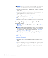
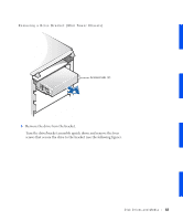
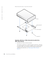
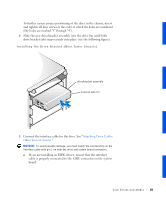
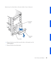
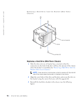
To further ensure proper positioning of the drive in the chassis, insert and tighten all four screws in the order in which the holes are numbered (the holes are marked "1" through "4"). 2 Slide the new drive/bracket assembly into the drive bay until both drive bracket tabs snap securely into place (see the following figure). Inst alli ng t he D rive Bracket (Mini Tower Chass is) drive/bracket assembly bracket tabs (2) 3 Connect the interface cable for the drive. See "Attaching Drive Cables (Mini Tower Chassis)." NOTICE: To avoid possible damage, you must match the colored strip on the interface cable with pin 1 on both the drive and system board connectors. a If you are installing an EIDE device, ensure that the interface cable is properly connected to the EIDE connector on the system board. Disk Dri ves and Media 85
-
 1
1 -
2
-
3
-
4
-
5
-
6
-
7
-
8
-
9
-
10
-
11
-
12
-
13
-
14
-
15
-
16
-
17
-
18
-
19
-
20
-
21
-
22
-
23
-
24
-
25
-
26
-
27
-
28
-
29
-
30
-
31
-
32
-
33
-
34
-
35
-
36
-
37
-
38
-
39
-
40
-
41
-
42
-
43
-
44
-
45
-
46
-
47
-
48
-
49
-
50
-
51
-
52
-
53
-
54
-
55
-
56
-
57
-
58
-
59
-
60
-
61
-
62
-
63
-
64
-
65
-
66
-
67
-
68
-
69
-
70
-
71
-
72
-
73
-
74
-
75
-
76
-
77
-
78
-
79
-
 80
80 -
 81
81 -
 82
82 -
 83
83 -
 84
84 -
 85
85 -
 86
86 -
 87
87 -
 88
88 -
 89
89 -
 90
90 -
91
-
92
-
93
-
94
-
95
-
96
-
97
-
98
-
99
-
100
-
101
-
102
-
103
-
104
-
105
-
106
-
107
-
108
-
109
-
110
-
111
-
112
-
113
-
114
-
115
-
116
-
117
-
118
-
119
-
120
-
121
-
122
-
123
-
124
-
125
-
126
-
127
-
128
-
129
-
130
-
131
-
132
-
133
-
134
-
135
-
136
-
137
-
138
-
139
-
140
-
141
-
142
-
143
-
144
-
145
-
146
-
147
-
148
-
149
-
150
-
151
-
152
-
153
-
154
-
155
-
156
-
157
-
158
-
159
-
160
-
161
-
162
-
163
-
164
-
165
-
166
-
167
-
168
-
169
-
170
 |
 |
