Dell S4148U-ON EMC Networking FCoE Deployment with S4148U-ON in NPG Mode - Page 9
Topology overview
 |
View all Dell S4148U-ON manuals
Add to My Manuals
Save this manual to your list of manuals |
Page 9 highlights
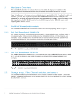
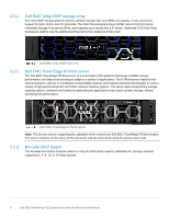
3 Topology overview Each S4148U-ON provides unified ports, configured as FC or Ethernet. The mix of FC and Ethernet ports allows the switches to simultaneously connect directly to an FC SAN for storage traffic and also act as a leaf in a leaf-spine network for production TCP/IP traffic. Note: FC SAN traffic does not traverse the leaf-spine network, or the VLT interconnect (VLTi). A combined FC SAN and leaf-spine topology are shown in the diagram below. 3.1 Combined FC SAN and leaf-spine topology Note: Using a leaf-spine network in the data center is considered a best practice. This document covers configuration of the FC SAN portion of the topology above. For the leaf-spine Ethernet portion, refer to Dell EMC Networking Layer 3 Leaf-Spine Deployment and Best Practices with OS10EE. FC SAN topology detail Each S4148U-ON switch is placed in NPG mode and provides FCoE to FC bridging. FC services are provided by the dedicated FC network. In this example, the FC switches are Brocade 6510 switches. The FC SAN topology used in this guide is shown in Figure 6. 9 Dell EMC Networking FCoE Deployment with S4148U-ON in NPG Mode
-
 1
1 -
2
-
3
-
 4
4 -
 5
5 -
 6
6 -
 7
7 -
 8
8 -
 9
9 -
 10
10 -
 11
11 -
 12
12 -
 13
13 -
 14
14 -
15
-
16
-
17
-
18
-
19
-
20
-
21
-
22
-
23
-
24
-
25
-
26
-
27
-
28
-
29
-
30
-
31
-
32
-
33
-
34
-
35
-
36
-
37
 |
 |
