Dell TL4000 User Guide - Page 10
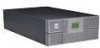
The Con Library: Drives for a, Height V2 drive and one Ultrium 4 SAS - tape library
 |
View all Dell TL4000 manuals
Add to My Manuals
Save this manual to your list of manuals |
Page 10 highlights
5-18. 5-19. 5-20. 5-21. 5-22. 5-23. 5-24. 5-25. 5-26. 5-27. 5-28. 5-29. 5-30. 5-31. 5-32. 5-33. 5-34. 5-35. 5-36. 5-37. 5-38. 5-39. 5-40. 5-41. 5-42. 5-43. 5-44. 5-45. 5-46. 5-47. 5-48. 5-49. 5-50. 5-51. 5-52. 5-53. 5-54. 5-55. 5-56. 5-57. 5-58. 5-59. Pound sign (#) shows accessible menus when access PIN is enabled but before it is entered 5-26 Configure: Save/Restore menu . . . . . 5-27 Configure: Set Date and Time menu 5-29 Configure: Path failover 5-29 Service: Library Verify menu . . . . . 5-30 Service: Run Tests menu 5-30 Service: Service menu 5-31 Service: Display Contrast menu 5-32 The 4U library Monitor Library: Library Identity page 5-34 The 4U library Monitor Library: Drive Identity page, showing one Ultrium 3 SAS half height V2 drive (#1) and one Ultrium 4 SAS half height drive (#2 5-36 The 4U library Monitor Library: Library Status page 5-37 The 4U library Monitor Library: Drive Status page 5-39 The 2U library Monitor Library: Inventory page 5-40 The 4U library Monitor Library: Inventory page (Right Magazines 5-41 Manage Library: move media page 5-42 Manage Library: Perform inventory page 5-42 Manage Library: Release Magazine page 5-42 The 4U library Configure Library: General and Extended page 5-44 The 4U library Configure Library: Logical Libraries page 5-45 The 4U library Configure Library: Path Failover page 5-45 Path Failover license verification page 5-45 The Configure Library: LTFS page 5-46 Feature Activation Key screen . . . . . 5-47 Configure Library: Encryption feature configuration screen 5-48 The Configure Library: Drives page for a 2U library 5-50 The Configure Library: Drives page for a 4U library 5-50 Configure Library: Network page 5-51 Warning screen 5-52 Configure Library: User Access page 5-53 The Configure Library: Date & Time page 5-54 Configure Library: Logs & Traces page 5-55 Configure Library: Event Notification page 5-55 Configure Library: SNMP page 5-57 Configure Library: Save/Restore page 5-58 No Cleaning Required 5-59 No cleaning cartridge in library 5-59 Service Library: Clean Drive page 5-59 Service Library: View Logs page 5-60 Service Library: View Drive Logs screen 5-61 Service: Save Drive Dump 5-62 Service Library: Perform Diagnostics page 5-62 Service Library: Perform Key Path Diagnostics page 5-63 5-60. The Service Library: Upgrade Firmware page, showing one Ultrium 3 SAS Half Height V2 drive and one Ultrium 4 SAS Half Height drive 5-65 5-61. Service Library: Reboot page . . . . . 5-65 6-1. The LTO Ultrium data cartridge . . . . . 6-1 6-2. Ultrium Data and WORM Tape Cartridges 6-3 6-3. Sample bar code label on the LTO Ultrium 6 Tape Cartridge 6-6 6-4. Setting the write-protect switch . . . . . 6-7 6-5. Double-boxing tape cartridges for shipping 6-8 6-6. Checking for gaps in the seams of a cartridge 6-9 7-1. A 250w power supply with LEDs 7-8 7-2. A 80w power supply without LEDs 7-8 9-1. Access holes for the left magazine 9-1 9-2. Access holes for the right magazine 9-2 9-3. Left magazine pulled out of the 2U library 9-3 9-4. Left Magazines pulled out of the 4U Library 9-3 10-1. ESD label 10-1 10-2. Shipping lock and label storage location 10-2 10-3. Shipping lock and label 10-2 10-4. Library drive sled without ElectroStatic Discharge (ESD) springs (SCSI sled shown) 10-3 10-5. Library drive sled with ESD springs [1] (SAS sled shown 10-3 10-6. Drive sled components (full height fibre drive in top position, half height SCSI drive in middle position, half height SAS drive in bottom position) on back panel of a 4U library 10-4 10-7. Pulling the drive sled out of the library (drive sled without ESD springs shown) . 10-5 10-8. Pushing the drive sled into the library (drive sled without ESD springs shown) . 10-6 10-9. Diagrams for applying conductive tape for ESD protection to the back of a drive sled installed in a 2U or 4U library . . . . . 10-7 10-10. A power supply removed from a 2U library 10-9 10-11. A library controller card that is removed from the library 10-11 10-12. Removing the two mounting bracket screws anchoring the library to the rack (one screw on each side of the library) . . 10-13 10-13. Foot pads that are installed on the bottom of the library enclosure 10-14 10-14. Removing the shipping label and lock from the top of the library and storing on the rear panel 10-15 10-15. Library shipping lock and label storage location on the real panel of the library . 10-15 10-16. Removing a drive sled from the library (drive sled without ESD springs shown) . 10-16 10-17. Drive sled taping diagrams . . . . . 10-17 10-18. A power supply that is removed from a library 10-18 10-19. Removing a library controller card from the library 10-20 10-20. Library front panel LEDs 10-21 viii Dell PowerVault TL2000 Tape Library and TL4000 Tape Library User's Guide
-
 1
1 -
2
-
3
-
4
-
 5
5 -
 6
6 -
 7
7 -
 8
8 -
 9
9 -
 10
10 -
 11
11 -
 12
12 -
 13
13 -
 14
14 -
 15
15 -
16
-
17
-
18
-
19
-
20
-
21
-
22
-
23
-
24
-
25
-
26
-
27
-
28
-
29
-
30
-
31
-
32
-
33
-
34
-
35
-
36
-
37
-
38
-
39
-
40
-
41
-
42
-
43
-
44
-
45
-
46
-
47
-
48
-
49
-
50
-
51
-
52
-
53
-
54
-
55
-
56
-
57
-
58
-
59
-
60
-
61
-
62
-
63
-
64
-
65
-
66
-
67
-
68
-
69
-
70
-
71
-
72
-
73
-
74
-
75
-
76
-
77
-
78
-
79
-
80
-
81
-
82
-
83
-
84
-
85
-
86
-
87
-
88
-
89
-
90
-
91
-
92
-
93
-
94
-
95
-
96
-
97
-
98
-
99
-
100
-
101
-
102
-
103
-
104
-
105
-
106
-
107
-
108
-
109
-
110
-
111
-
112
-
113
-
114
-
115
-
116
-
117
-
118
-
119
-
120
-
121
-
122
-
123
-
124
-
125
-
126
-
127
-
128
-
129
-
130
-
131
-
132
-
133
-
134
-
135
-
136
-
137
-
138
-
139
-
140
-
141
-
142
-
143
-
144
-
145
-
146
-
147
-
148
-
149
-
150
-
151
-
152
-
153
-
154
-
155
-
156
-
157
-
158
-
159
-
160
-
161
-
162
-
163
-
164
-
165
-
166
-
167
-
168
-
169
-
170
-
171
-
172
-
173
-
174
-
175
-
176
-
177
-
178
-
179
-
180
-
181
-
182
-
183
-
184
-
185
-
186
-
187
-
188
-
189
-
190
-
191
-
192
-
193
-
194
-
195
-
196
-
197
-
198
-
199
-
200
-
201
-
202
-
203
-
204
-
205
-
206
-
207
-
208
-
209
-
210
-
211
-
212
-
213
-
214
-
215
-
216
-
217
-
218
-
219
-
220
-
221
-
222
-
223
-
224
-
225
-
226
-
227
-
228
-
229
-
230
-
231
-
232
-
233
-
234
-
235
-
236
-
237
-
238
-
239
-
240
-
241
-
242
-
243
-
244
-
245
-
246
-
247
-
248
-
249
-
250
-
251
-
252
-
253
-
254
-
255
-
256
-
257
-
258
-
259
-
260
-
261
-
262
-
263
-
264
-
265
-
266
-
267
-
268
-
269
-
270
-
271
-
272
-
273
-
274
-
275
-
276
-
277
-
278
-
279
-
280
-
281
-
282
-
283
-
284
-
285
-
286
-
287
-
288
-
289
-
290
-
291
-
292
-
293
-
294
-
295
-
296
 |
 |
