Dell Vostro 16 5635 Owners Manual - Page 68
Connect the touchpad cable to the system board and close the latch.
 |
View all Dell Vostro 16 5635 manuals
Add to My Manuals
Save this manual to your list of manuals |
Page 68 highlights
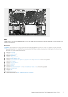
Steps 1. Install the system board at an angle and ensure that the ports are properly aligned with the port openings. 2. Place the system board on the palm-rest and keyboard assembly. 3. Align the screw holes on the system board with the screw holes on the palm-rest and keyboard assembly. 4. Replace the two screws (M2x1.8) that secure the system board to the palm-rest and keyboard assembly. 5. Connect the fan cable to the system board. 6. Connect the I/O board cable to the system board and close the latch. 7. Connect the keyboard-backlight cable to the system board. 8. Connect the touchpad cable to the system board and close the latch. 9. Connect the keyboard cable to the system board and close the latch. 10. Connect the battery cable to the system board. 11. Align the screw holes of the Type-C port-bracket with the screw holes of the system board. 12. Place the Type-C port-bracket on the system board. 68 Removing and installing Field Replaceable Units (FRUs)
-
 1
1 -
2
-
3
-
4
-
5
-
6
-
7
-
8
-
9
-
10
-
11
-
12
-
13
-
14
-
15
-
16
-
17
-
18
-
19
-
20
-
21
-
22
-
23
-
24
-
25
-
26
-
27
-
28
-
29
-
30
-
31
-
32
-
33
-
34
-
35
-
36
-
37
-
38
-
39
-
40
-
41
-
42
-
43
-
44
-
45
-
46
-
47
-
48
-
49
-
50
-
51
-
52
-
53
-
54
-
55
-
56
-
57
-
58
-
59
-
60
-
61
-
62
-
 63
63 -
 64
64 -
 65
65 -
 66
66 -
 67
67 -
 68
68 -
 69
69 -
 70
70 -
 71
71 -
 72
72 -
 73
73 -
74
-
75
-
76
-
77
-
78
-
79
-
80
-
81
-
82
-
83
-
84
-
85
-
86
-
87
-
88
-
89
-
90
-
91
-
92
-
93
-
94
-
95
 |
 |
