Dell Vostro 410 Service Manual
Dell Vostro 410 Manual
 |
View all Dell Vostro 410 manuals
Add to My Manuals
Save this manual to your list of manuals |
Dell Vostro 410 manual content summary:
- Dell Vostro 410 | Service Manual - Page 1
Dell™ Vostro™ 410 Service Manual Troubleshooting Computer Cover PCI and PCI Express Cards I/O Panel Memory Processor System Board Contacting Dell Working on Your Computer Bezel Drives Fans Battery Power Supply System Setup Notes, Notices, and Cautions NOTE: A NOTE indicates important information - Dell Vostro 410 | Service Manual - Page 2
Back to Contents Page Bezel Dell™ Vostro™ 410 Service Manual Removing the Bezel Replacing the Bezel CAUTION: Before working inside your computer, read the safety information that shipped with your computer. For additional safety best practices information, see the Regulatory Compliance Homepage at - Dell Vostro 410 | Service Manual - Page 3
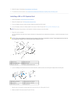
1 bezel clamp (3) 3 bezel grip (4) 2 bezel 4 bezel clamp slots (3) 2. Rotate the front cover toward the computer until it bezel grips on the left edge of the cover snap into place. 3. Perform the steps in the procedure After Working on Your Computer. Back to Contents Page - Dell Vostro 410 | Service Manual - Page 4
Page PCI and PCI Express Cards Dell™ Vostro™ 410 Service Manual Removing a PCI or PCI Express Card Installing a PCI or PCI Express Card Configuring Your Computer After Removing or Installing a PCI or PCI Express Card CAUTION: Before working inside your computer, read the safety information that - Dell Vostro 410 | Service Manual - Page 5
the removal procedure, see Configuring Your Computer After Removing or Installing a PCI or PCI Express Card. Installing a PCI or PCI Express Card 1. Follow the procedures in Before Working on Your Computer. 2. Remove the computer cover. See Removing the Computer Cover. 3. If you are installing a new - Dell Vostro 410 | Service Manual - Page 6
. 11. Perform the steps in the procedure After Working on Your Computer. 12. Install any drivers required for the card as described in the card documentation. Configuring Your Computer After Removing or Installing a PCI or PCI Express Card NOTE: For information on location of connectors, see - Dell Vostro 410 | Service Manual - Page 7
Back to Contents Page Battery Dell™ Vostro™ 410 Service Manual Removing the Battery Replacing the Battery CAUTION: Before working inside your computer, read the safety information that shipped with your computer. For additional safety best practices information, see the Regulatory Compliance - Dell Vostro 410 | Service Manual - Page 8
Back to Contents Page Contacting Dell Dell™ Vostro™ 410 Service Manual To contact Dell for sales, technical support, or customer service issues: 1. Visit support.dell.com. 2. Verify your country or region in the Choose a Country/Region drop-down menu at the bottom of the page. 3. Click Contact Us on - Dell Vostro 410 | Service Manual - Page 9
Back to Contents Page Computer Cover Dell™ Vostro™ 410 Service Manual Removing the Computer Cover Replacing the Computer Cover CAUTION: Before working inside your computer, read the safety information that shipped with your computer. For additional safety best practices information, see the - Dell Vostro 410 | Service Manual - Page 10
7. Follow the procedures in After Working on Your Computer. Back to Contents Page - Dell Vostro 410 | Service Manual - Page 11
Back to Contents Page Processor Dell™ Vostro™ 410 Service Manual Removing the Processor Replacing the Processor CAUTION: Before working inside your computer, read the safety information that shipped with your computer. For additional safety best practices information, see the Regulatory Compliance - Dell Vostro 410 | Service Manual - Page 12
that the processor fan and heat sink assembly is correctly seated and secure. 12. Perform the steps in the procedure After Working on Your Computer. 13. Verify that your computer works correctly by running the Dell Diagnostics. See your Setup and Quick Reference Guide for help with Dell Diagnostics - Dell Vostro 410 | Service Manual - Page 13
- Dell Vostro 410 | Service Manual - Page 14
Back to Contents Page Drives Dell™ Vostro™ 410 Service Manual About the Drives in Your Computer Hard Drives Floppy Drive Media Card Reader Optical Drive CAUTION: Before working inside your computer, read the safety information that shipped with your computer. For additional safety best practices - Dell Vostro 410 | Service Manual - Page 15
-in hole on the other connector. Hard Drives CAUTION: Before working inside your computer, read the safety information that shipped with your computer. For additional safety best practices information, see the Regulatory Compliance Homepage at www.dell.com/regulatory_compliance. CAUTION: To guard - Dell Vostro 410 | Service Manual - Page 16
Perform the steps in the procedure After Working on Your Computer. Replacing or Adding a Hard Drive 1. Follow the procedures in Before Working on Your Computer. 2. Remove the computer cover (see Removing the Computer Cover). 3. Check the documentation for the drive to verify that it is configured - Dell Vostro 410 | Service Manual - Page 17
slot 5 power cable 2 hard drive 4 screws (2), partially inserted 6 data cable 7. Connect the power and data cables to the drive. 8. Connect the data cable to the system board. 9. Check all cables to be certain that they are properly connected and firmly seated. 10. Replace the computer cover (see - Dell Vostro 410 | Service Manual - Page 18
out through the front of the computer. 8. If you are not replacing the drive, reinstall the drive panel insert (see Media Card Reader). 9. Replace the bezel (see Replacing the Computer Cover). 10. Perform the steps in the procedure After Working on Your Computer. 11. Check the system setup for the - Dell Vostro 410 | Service Manual - Page 19
of the way to avoid blocking airflow between the fan and cooling vents. 11. Replace the bezel (see Replacing the Bezel). 12. Perform the steps in the procedure After Working on Your Computer. 13. See the documentation that came with the drive for instructions on installing any software required for - Dell Vostro 410 | Service Manual - Page 20
the floppy drive is removed from the computer. Media Card Reader CAUTION: Before working inside your computer, read the safety information that shipped with your computer. For additional safety best practices information, see the Regulatory Compliance Homepage at www.dell.com/regulatory_compliance - Dell Vostro 410 | Service Manual - Page 21
and to the internal USB connector on the system board (see System Board Components). 1 screws (2) 3 Media Card Reader 2 screw slots (2) 4 USB interface cable 10. Replace the bezel (see Replacing the Bezel). 11. Perform the steps in the procedure After Working on Your Computer. Optical Drive - Dell Vostro 410 | Service Manual - Page 22
the computer. 11. Connect your computer and devices to electrical outlets, and then turn them on. 12. Configure the drives in system setup (see Entering System Setup). Replacing or Adding an Optical Drive 1. Follow the procedures in Before Working on Your Computer. 2. Remove the computer cover - Dell Vostro 410 | Service Manual - Page 23
the drive for instructions on installing any software required for drive operation. 12. Enter system setup and select the appropriate Drive option (see Entering System Setup). 13. Verify that your computer works correctly by running the Dell Diagnostics. See your Setup and Quick Reference Guide for - Dell Vostro 410 | Service Manual - Page 24
place. CAUTION: To comply with FCC regulations, it is recommended that you replace the optical panel insert whenever the optical disc is removed from the computer. Back to Contents Page - Dell Vostro 410 | Service Manual - Page 25
to Contents Page Fans Dell™ Vostro™ 410 Service Manual Remove the Processor Heat Sink Assembly Replacing the Processor Heat Sink Assembly Remove the Chassis Fan Replacing the Chassis Fan CAUTION: Before working inside your computer, read the safety information that shipped with your computer. For - Dell Vostro 410 | Service Manual - Page 26
). 6. Perform the steps in the procedure After Working on Your Computer. Remove the Chassis Fan 1. Follow the procedures in Before Working on Your Computer. 2. Remove the computer cover (see Removing the Computer Cover). 3. Disconnect the chassis fan cable from the system board. 4. While holding - Dell Vostro 410 | Service Manual - Page 27
1 chassis fan 3 screw (4) 2 system board power connector Replacing the Chassis Fan 1. If not already done, remove the computer cover (see Removing the Computer Cover). 2. While holding the chassis fan in place, install the four screws that secure the fan to the chassis. 1 chassis fan 2 screw - Dell Vostro 410 | Service Manual - Page 28
Back to Contents Page I/O Panel Dell™ Vostro™ 410 Service Manual Removing the I/O Panel Replacing the I/O Panel CAUTION: Before working inside your computer, read the safety information that shipped with your computer. For additional safety best practices information, see the Regulatory Compliance - Dell Vostro 410 | Service Manual - Page 29
the Bezel). 5. Perform the steps in the procedure After Working on Your Computer. 6. Verify that the computer works correctly by running the Dell Diagnostics. See your Setup and Quick Reference Guide for help running the Dell Diagnostics. 1 I/O panel screw hole 3 screw Back to Contents Page - Dell Vostro 410 | Service Manual - Page 30
Back to Contents Page Memory Dell™ Vostro™ 410 Service Manual Removing Memory Modules Replacing or Adding a Memory Module CAUTION: Before working inside your computer, read the safety information that shipped with your computer. For additional safety best practices information, see the Regulatory - Dell Vostro 410 | Service Manual - Page 31
in the procedure After Working on Your Computer. 4. Log on to your computer. 5. Right-click the My Computer icon on your Windows desktop and click Properties. 6. Click the General tab. 7. To verify that the memory is installed correctly, check the amount of memory (RAM) listed. Back to Contents - Dell Vostro 410 | Service Manual - Page 32
Back to Contents Page Power Supply Dell™ Vostro™ 410 Service Manual Removing the Power Supply Replacing the Power Supply Power Supply DC Connector Pin Assignments CAUTION: Before working inside your computer, read the safety information that shipped with your computer. For additional safety best - Dell Vostro 410 | Service Manual - Page 33
the computer works correctly by running the Dell Diagnostics. See your Setup and Quick Reference Guide for help running Dell Diagnostics. CAUTION: Failure to replace and tighten all screws may cause electrical shock as these screws are a key part of the system grounding. Power Supply DC Connector - Dell Vostro 410 | Service Manual - Page 34
DC Power Connector P1 Pin Number Signal name Wire Color Wire Size 1 3.3 V Orange 20 AWG 2 3.3 V Orange 20 22 5 V Red 20 AWG 23 5 V Red 20 AWG 24 RTN Black 20 AWG DC Power Connector P2 Pin Number Signal Name 18-AWG Wire 1 GND Black 2 GND Black 3 +12 VADC Yellow 4 +12 VADC - Dell Vostro 410 | Service Manual - Page 35
Connector P9 Pin Number Signal Name 22-AWG Wire 1 +5 VDC Red 2 GND Black 3 GND Black 4 +12 VADC Yellow DC Power Connector P10 Pin Number Signal Name 22-AWG Wire 1 +12 VDC Yellow 2 +12 VDC Yellow 3 +12 VDC Yellow 4 GND Black 5 GND Black 6 GND Black Back - Dell Vostro 410 | Service Manual - Page 36
Back to Contents Page System Board Dell™ Vostro™ 410 Service Manual Remove the System Board Replacing a System Board CAUTION: Before working inside your computer, read the safety information that shipped with your computer. For additional safety best practices information, see the Regulatory - Dell Vostro 410 | Service Manual - Page 37
Working on Your Computer. 2. Set the computer on its right side on a clean and flat surface. 3. Remove the computer cover if necessary (see Removing the Computer board removal. Avoid over-tightening the screws. CAUTION: Failure to replace and tighten all screws properly may not provide adequate - Dell Vostro 410 | Service Manual - Page 38
6. Connect the 12V DC power cable to the system board. 7. Connect the chassis fan cable to the system board. 8. Connect all front panel and FlexBay device cables to the system board. 9. Connect all the data cables from the CD/DVD/hard drives to the system board. 10. If the system board is being - Dell Vostro 410 | Service Manual - Page 39
Back to Contents Page System Setup Dell™ Vostro™ 410 Service Manual Overview Entering System Setup System Setup Screens System Setup Options Boot Sequence Clearing Forgotten Passwords Clearing CMOS Settings Flashing the BIOS Overview Use system setup as follows: l To change the system configuration - Dell Vostro 410 | Service Manual - Page 40
by default) Third Boot Device Removable; Hard Disk; CDROM; USB-CDROM; Legacy LAN; Disabled (CD-ROM by default) Boot Other Device Enabled; Disabled (Disabled by default) Advanced Chipset Features Init Display First PCI Slot, Onboard, PCIEx (PCI Slot by default) Video Memory Size 1 MB, 8 MB - Dell Vostro 410 | Service Manual - Page 41
Dell Drivers and Utilities media, but you want the computer to boot from the hard drive when the diagnostic tests are complete. You can also use this feature to restart your computer to a USB device such as a floppy drive, memory key, or CD-RW drive. 1. If you are booting to a USB device, connect - Dell Vostro 410 | Service Manual - Page 42
your computer and devices to electrical outlets, and turn them on. Clearing CMOS Settings CAUTION: Before working inside your computer, read the safety information that shipped with your computer. For additional safety best practices information, see the Regulatory Compliance Homepage at www.dell - Dell Vostro 410 | Service Manual - Page 43
Flashing the BIOS The BIOS may require flashing when an update is available or when replacing the system board. 1. Turn on the computer. 2. Locate the BIOS update file for your computer at the Dell Support website at support.dell.com. 3. Click Download Now to download the file. 4. If the Export - Dell Vostro 410 | Service Manual - Page 44
to Contents Page Dell™ Vostro™ 410 Service Manual Notes, Notices, and Cautions NOTE: A NOTE indicates important information that helps you make better use of your computer. NOTICE: A NOTICE indicates either potential damage to hardware or loss of data and tells you how to avoid the problem. CAUTION - Dell Vostro 410 | Service Manual - Page 45
to Contents Page Troubleshooting Dell™ Vostro™ 410 Service Manual Tools Dell Diagnostics Solving Problems Dell Technical Update Service Dell Support Utility Tools Power Lights CAUTION: Before working inside your computer, read the safety information that shipped with your computer. For additional - Dell Vostro 410 | Service Manual - Page 46
Hard-disk read failure - Possible HDD failure during HDD boot test (see Contacting Dell). Keyboard failure - Keyboard failure or keyboard cable loose (see Keyboard Problems). No boot device available - The system cannot detect a bootable device or partition. ¡ If the floppy drive is your boot device - Dell Vostro 410 | Service Manual - Page 47
safety instructions located that shipped with your computer. When to Use the Dell Diagnostics If you experience a problem with your computer, perform the checks in this section, and then run the Dell Diagnostics before contacting Dell for assistance. Start the Dell Diagnostics from your hard drive - Dell Vostro 410 | Service Manual - Page 48
Windows desktop, then shut down your computer and try again. 4. When the boot device list appears, use the up- or down- arrow keys to highlight CD/DVD/CD-RW Drive then press . NOTE: Using the one-time boot menu changes the boot sequence for the current boot only. Upon restart, the computer - Dell Vostro 410 | Service Manual - Page 49
down the error code and problem description exactly as it appears and follow the instructions on the screen. If you cannot resolve the problem, contact Dell (see Contacting Dell). NOTE: When contacting Dell support, have your Service Tag ready. The Service Tag for your computer is located at the - Dell Vostro 410 | Service Manual - Page 50
still does not work properly, contact Dell (see Contacting Dell). Drive Problems CAUTION: Before you begin any of the procedures in this section, follow the safety instructions that shipped with your computer. Ensure that Microsoft® Windows® Recognizes the drive - Windows XP: l Click Start and - Dell Vostro 410 | Service Manual - Page 51
before writing to a disc - See the Dell Technology Guide, or search for the keyword standby in Windows Help and Support for information on power management modes. Hard drive problems Run Check Disk - Windows XP: 1. Click Start and click My Computer. 2. Right-click Local Disk C:. 3. Click Properties - Dell Vostro 410 | Service Manual - Page 52
Operating system not found - Contact Dell (see Contacting Dell). IEEE 1394 Device Problems CAUTION: Before you begin any of the procedures in this section, follow the safety instructions that shipped with your computer. NOTE: Your computer supports only IEEE 1394a standard. Ensure that the cable for - Dell Vostro 410 | Service Manual - Page 53
with this version of Windows. 2. In the welcome screen, click Next. 3. Follow the instructions on the screen. A solid blue screen appears Turn the computer off - If you are unable to get a response by pressing a key on your keyboard or moving your mouse, press and hold the power button for at least - Dell Vostro 410 | Service Manual - Page 54
to check the hard drive, floppy disks, CDs, or DVDs Save and close any open files or programs and shut down your computer through the Start menu Memory Problems CAUTION: Before you begin any of the procedures in this section, follow the safety instructions that shipped with your computer. If you - Dell Vostro 410 | Service Manual - Page 55
with another device, such as a lamp. l Ensure that the main power cable and front panel cable are securely connected to the system board (see System Board Components). If the power light is blinking amber, beep code 3 - The computer is receiving electrical power, but a system board failure may exist - Dell Vostro 410 | Service Manual - Page 56
. 2. If the scanner is listed, Windows recognizes the scanner. Reinstall the scanner driver - See the scanner documentation for instructions. Sound and Speaker Problems CAUTION: Before you begin any of the procedures in this section, follow the safety instructions that shipped with your computer. - Dell Vostro 410 | Service Manual - Page 57
the sound is not muted. Video and Monitor Problems CAUTION: Before you begin any of the procedures in this section, follow the safety instructions that shipped with your computer. NOTICE: If your computer came with a PCI graphics card installed, removal of the card is not necessary when installing - Dell Vostro 410 | Service Manual - Page 58
If the external monitor works, the computer display or video controller may be defective. Contact Dell (see Contacting Dell). Dell Technical Update Service The Dell Technical Update service provides proactive e-mail notification of software and hardware updates for your computer. The service is free - Dell Vostro 410 | Service Manual - Page 59
, , icon on the taskbar or from the Start button. Use this support utility for self-support information, software updates, and health scans of your computing environment. Accessing the Dell Support Utility Access the Dell Support Utility from the icon on the taskbar or from the Start menu. If - Dell Vostro 410 | Service Manual - Page 60
Back to Contents Page Working on Your Computer Dell™ Vostro™ 410 Service Manual Recommended Tools Before Working on Your Computer Inside View of Your Computer System Board Components After Working on Your Computer This document provides procedures for removing and installing the components in your - Dell Vostro 410 | Service Manual - Page 61
of Your Computer 1 power supply 3 optional optical drive bays 5 USB, audio, 1394 (optional) connectors 7 chassis fan ` 2 optical drive bay 4 floppy drive or Media Reader (optional) 6 3.5-inch drive bays (4) System Board Components 1 power connector (PWR2) 2 CPU fan power 4 main power connector - Dell Vostro 410 | Service Manual - Page 62
x16 connector (PCIE_x16) 26 audio connectors 27 one LAN and two USB ports 28 CPU fan power 29 USB ports (2) 30 video connector (VGA) After Working on Your Computer After you have completed any replacement procedures, ensure you connect any external devices, cards, cables, etc. before turning
-
 1
1 -
 2
2 -
 3
3 -
 4
4 -
 5
5 -
 6
6 -
 7
7 -
8
-
9
-
10
-
11
-
12
-
13
-
14
-
15
-
16
-
17
-
18
-
19
-
20
-
21
-
22
-
23
-
24
-
25
-
26
-
27
-
28
-
29
-
30
-
31
-
32
-
33
-
34
-
35
-
36
-
37
-
38
-
39
-
40
-
41
-
42
-
43
-
44
-
45
-
46
-
47
-
48
-
49
-
50
-
51
-
52
-
53
-
54
-
55
-
56
-
57
-
58
-
59
-
60
-
61
-
62
 |
 |
Dell™ Vostro™ 410 Service Manual
Notes, Notices, and Cautions
If you purchased a DELL™ n Series computer, any references in this document to Microsoft
®
Windows
®
operating systems are not applicable.
Information in this document is subject to change without notice.
© 2008 Dell Inc. All rights reserved.
Reproduction in any manner whatsoever without the written permission of Dell Inc. is strictly forbidden.
Trademarks used in this text:
Dell
, the
DELL
logo, and
Vostro
are trademarks of Dell Inc.;
Microsoft
,
Windows, Windows Vista, and the Windows
start
button logo
are either trademarks
or registered trademarks of Microsoft Corporation in the United States and/or other countries.
Bluetooth
is a registered trademark of Bluetooth SIG Inc.
Other trademarks and trade names may be used in this document to refer to either the entities claiming the marks and names or their products. Dell Inc. disclaims any
proprietary interest in trademarks and trade names other than its own.
Model DCGAF
August 2008
Rev. A00
Troubleshooting
Working on Your Computer
Computer Cover
Bezel
PCI and PCI Express Cards
Drives
I/O Panel
Fans
Memory
Battery
Processor
Power Supply
System Board
System Setup
Contacting Dell
NOTE:
A NOTE indicates important information that helps you make better use of your computer.
NOTICE:
A NOTICE indicates either potential damage to hardware or loss of data and tells you how to avoid the problem.
CAUTION:
A CAUTION indicates potential for property damage, personal injury, or death.