Dell Vostro 410 Service Manual - Page 28
I/O Panel
 |
View all Dell Vostro 410 manuals
Add to My Manuals
Save this manual to your list of manuals |
Page 28 highlights
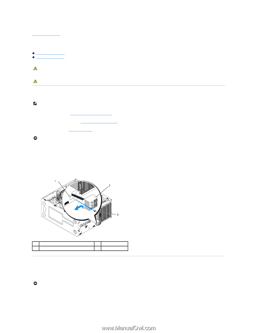
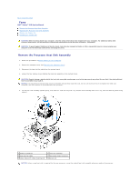
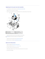
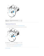
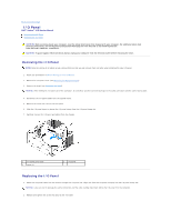
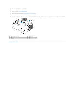
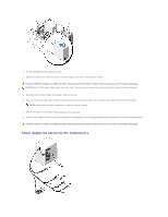
Back to Contents Page I/O Panel Dell™ Vostro™ 410 Service Manual Removing the I/O Panel Replacing the I/O Panel CAUTION: Before working inside your computer, read the safety information that shipped with your computer. For additional safety best practices information, see the Regulatory Compliance Homepage on www.dell.com at the following location: www.dell.com/regulatory_compliance. CAUTION: To guard against electrical shock, always unplug your computer from the electrical outlet before removing the cover. Removing the I/O Panel NOTE: Note the routing of all cables as you remove them so that you can reroute them correctly when installing the new I/O panel. 1. Follow the procedures in Before Working on Your Computer. 2. Remove the computer cover (see Removing the Computer Cover). 3. Remove the bezel (see Removing the Bezel). NOTICE: When sliding the I/O panel out of the computer, be extremely careful to prevent damage to the cable connectors and the cable routing clips. 4. Disconnect the I/O panel cables from the system board. 5. Remove the screw that secures the I/O panel. 6. Slide the I/O panel down to release the I/O panel clamp from the I/O panel clamp slot. 7. Carefully remove the I/O panel and cables from the chassis. 1 I/O panel screw hole 3 screw (1) 2 I/O panel Replacing the I/O Panel 1. Route the I/O panel cables into the chassis through the I/O panel slot. Align and slide the I/O panel clamp up into the I/O panel clamp slot. NOTICE: Take care not to damage the cable connectors and the cable routing clips when sliding the I/O panel into the computer. 2. Replace and tighten the screw that secures the I/O panel.
-
 1
1 -
2
-
3
-
4
-
5
-
6
-
7
-
8
-
9
-
10
-
11
-
12
-
13
-
14
-
15
-
16
-
17
-
18
-
19
-
20
-
21
-
22
-
 23
23 -
 24
24 -
 25
25 -
 26
26 -
 27
27 -
 28
28 -
 29
29 -
 30
30 -
 31
31 -
 32
32 -
 33
33 -
34
-
35
-
36
-
37
-
38
-
39
-
40
-
41
-
42
-
43
-
44
-
45
-
46
-
47
-
48
-
49
-
50
-
51
-
52
-
53
-
54
-
55
-
56
-
57
-
58
-
59
-
60
-
61
-
62
 |
 |