Dell W-7205 Controller Installation Guide - Page 11
Dual-Media Ports, 10/100/1000BASE-T (RJ-45) Ports
 |
View all Dell W-7205 manuals
Add to My Manuals
Save this manual to your list of manuals |
Page 11 highlights
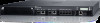
The following table lists the different components of the W-7205 controller: Table 4: W-7205 Controller Components Component Description Dual-Media ports 4 x dual-media (10/100/1000BASE-T and 1000BASE-X) ports 10GBASE-X ports 2 x 10GBASE-X ports USB interface Allows uploading configuration and image from a USB 2.0 storage device. Serial console port RJ-45 serial console access port for direct local management Micro-USB console port Micro-USB console access port for direct local management Management port Allows connection to a separate management network Power, Status, and Peered LED Provides basic monitoring of the controller LCD Allows configuration of LCD behavior and other basic operations Enter button Allows execution of actions on the LCD Screen Menu button Allows selection of the LCD screen menu CPU Module CPU module Power and Status LEDs on the CPU module Provides basic monitoring of the CPU module USB Interface on the CPU module Serves the same purpose as the USB interface on the front panel AC in AC power connector Grounding points Provided for attaching the grounding Page 11 13 15 15 16 16 17 17 19 19 19 Dual-Media Ports The W-7205 controller is equipped with four sets of dual-media ports (ports 0 through 3). These ports can utilize either a 1000BASE-X or 10/100/1000BASE-T connection provided. However, the 1000BASE-X fiber connection has priority over the 10/100/1000BASE-T copper connection. If a link is detected on the 1000BASE-X interface, the 10/100/1000BASE-T connection will be disabled. 10/100/1000BASE-T (RJ-45) Ports The W-7205 controller is equipped with four 10/100/1000BASE-T copper ports, as a part of dual-media ports. Gigabit Ethernet uses all eight wires and each pair is used in a bi-directional fashion, meaning the same pairs are used for both data transmission and reception. Figure 3 illustrates the CAT-5 pin-out on an RJ-45 connector. The CAT-5 pin-out pairs the following pins on a 10/100/1000BASE-T Gigabit Ethernet port: 1/2, 3/ 6, 4/5, and 7/8. Dell Networking W-7205 Controller | Installation Guide W-7205 Controller | 11
-
 1
1 -
2
-
3
-
4
-
5
-
 6
6 -
 7
7 -
 8
8 -
 9
9 -
 10
10 -
 11
11 -
 12
12 -
 13
13 -
 14
14 -
 15
15 -
 16
16 -
17
-
18
-
19
-
20
-
21
-
22
-
23
-
24
-
25
-
26
-
27
-
28
-
29
-
30
-
31
-
32
-
33
-
34
-
35
-
36
 |
 |
