Denon 4802R Owners Manual - Page 10
Connecting the antenna terminals, AM loop antenna assembly, Connection of AM antennas - remote
 |
UPC - 081757505345
View all Denon 4802R manuals
Add to My Manuals
Save this manual to your list of manuals |
Page 10 highlights
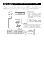
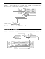
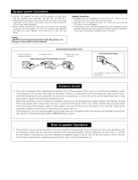
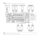
Connecting the antenna terminals DIRECTION OF BROADCASTING STATION F-type converter plug (attached) • When using the FM antenna attach to this apparatus 75 Ω/ohms COAXIAL CABLE FM ANTENNA FEEDER CABLE FM INDOOR ANTENNA (Supplied) 300 Ω/ohms AM LOOP ANTENNA (Supplied) SPEAKER SYSTEMS FRONT R CENTER SURROUND -A R LOOP ANT. AM IN DVD PRE OUT Y FR FL IN PB/CB PR/CR FM COAX. 75Ω SW SR C DVD VDP TV SL SURROUND -B R SB / MULTI R SBR ANTENNA SIGNAL PHONO GND L SBL I CD DVD VDP TV POWER AMP OUT OUT IN ROOM TO ROOM REMOTE CONTROL R EXT. IN FRONT CENTER SURROUND SB L R SW AM OUTDOOR ANTENNA GROUND AM loop antenna assembly Connect to the AM antenna terminals. 1 2 3 Remove the vinyl tie and take out the connection line. 4 a. With the antenna on top any stable surface. Bend in the reverse direction. Mount b. With the antenna attached to a wall. Installation hole Mount on wall, etc. Connection of AM antennas 1. Loosen by turning 2. Insert the cord. 3. Tighten by turning counterclockwise. clockwise. Note to CATV system installer: This reminder is provided to call the CATV system installer's attention to Article 820-40 of the NEC which provides guidelines for proper grounding and, in particular, specifies that the cable ground shall be connected to the grounding system of the building, as close to the point of cable entry as practical. Notes: • Do not connect two FM antennas simultaneously. • Even if an external AM antenna is used, do not disconnect the AM loop antenna. • Make sure AM loop antenna lead terminals do not touch metal parts of the panel. 10
-
 1
1 -
2
-
3
-
4
-
 5
5 -
 6
6 -
 7
7 -
 8
8 -
 9
9 -
 10
10 -
 11
11 -
 12
12 -
 13
13 -
 14
14 -
 15
15 -
16
-
17
-
18
-
19
-
20
-
21
-
22
-
23
-
24
-
25
-
26
-
27
-
28
-
29
-
30
-
31
-
32
-
33
-
34
-
35
-
36
-
37
-
38
-
39
-
40
-
41
-
42
-
43
-
44
-
45
-
46
-
47
-
48
-
49
-
50
-
51
-
52
-
53
-
54
-
55
-
56
-
57
-
58
-
59
-
60
-
61
-
62
-
63
-
64
-
65
-
66
-
67
-
68
-
69
-
70
-
71
-
72
-
73
-
74
-
75
-
76
-
77
-
78
-
79
-
80
-
81
-
82
-
83
-
84
-
85
-
86
-
87
-
88
-
89
-
90
 |
 |
