Denon 4802R Owners Manual - Page 16
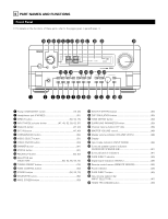
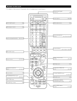
SETTING UP THE SYSTEM, SYSTEM SETUP button, ENTER button, CURSOR buttons - avr 7 1 channel receiver
 |
UPC - 081757505345
View all Denon 4802R manuals
Add to My Manuals
Save this manual to your list of manuals |
Page 16 highlights
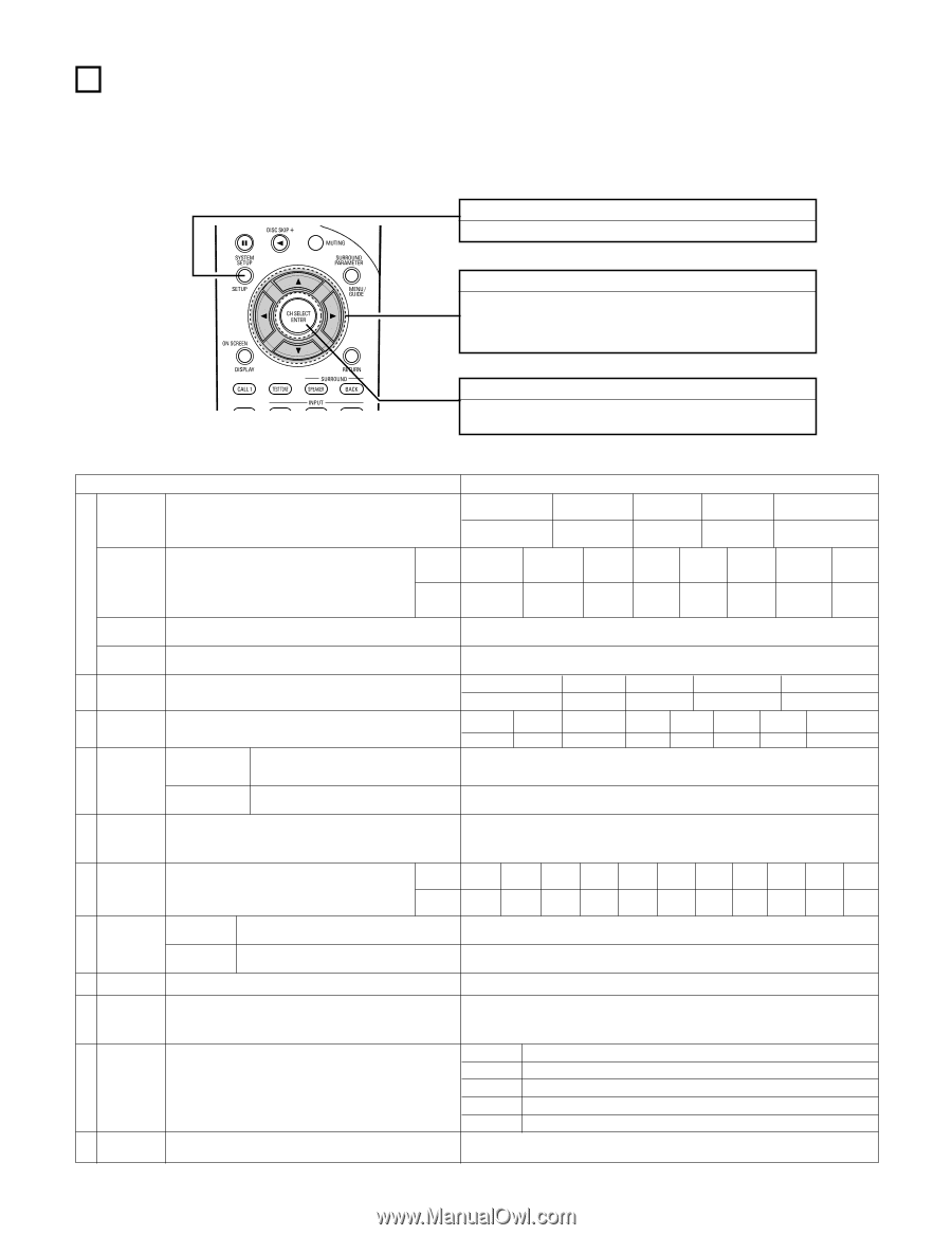
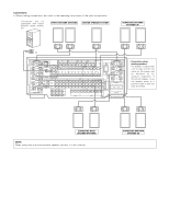
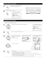
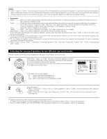
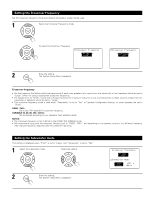
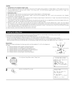
7 SETTING UP THE SYSTEM • Once all connections with other AV components have been completed as described in "CONNECTIONS" (see pages 6 to 13), make the various settings described below on the monitor screen using the AVR-4802R's on-screen display function. These settings are required to set up the listening room's AV system centered around the AVR-4802R. • Use the following buttons to set up the system: • Check that the remote control unit is set to AMP mode. SYSTEM SETUP button Press this to display the system setup menu. CURSOR buttons 0 and 1: • and ª: Use these to move the cursors (0 and 1) to the left and right on the screen. Use these to move the cursors (• and ª) to the up and down on the screen. ENTER button Press this to switch the display. Also use this button to complete the setting. • System setup items and default values (set upon shipment from the factory) System setup Default settings Speaker Configuration Surround q Speaker Setting Crossover Frequency Subwoofer mode w Delay Time e Channel Level r THX Audio Setup Subwoofer t Peak Limit Lev y Digital In Assignment u Multi Zone Control i Audio Delay Input the combination of speakers in your system and their corresponding sizes (Small for regular speakers, Large for fullsize, full-range) to automatically set the composition of the signals output from the speakers and the frequency response. Front Sp. Small Center Sp. Small Subwoofer Yes Surround Sp. Small Surround Back Sp. Small / 2spkrs Use this function when using multiple surround speaker Surround combinations for more ideal surround sound. Once the mode combinations of surround speakers to be used for the DOLBY/ DTS SURROUND THX / THX 5.1 WIDE SCREEN 5CH/7CH DSP STEREO SIMULATION EXT. IN - - different surround modes are preset, the surround speakers are selected automatically according to the Surround surround mode. speaker A A A A A A - - Set the frequency (Hz) below which the bass sound of the various speakers is to be output from the subwoofer. FIXED -THX- This selects the subwoofer speaker for playing deep bass signals. (see page 20) This parameter is for optimizing the timing with which the audio signals are produced from the speakers and subwoofer according to the listening position. This adjusts the volume of the signals output from the speakers and subwoofer for the different channels in order to obtain optimum effects. Boundary Gain compensation When using a THX Ultra2 compatible subwoofer, set the subwoofer's frequency response. LFE -THX- Front L & R 12 ft (3.6 m) Front L 0 dB Front R 0 dB Center 12 ft (3.6 m) Center 0 dB Subwoofer Surround L & R SBL & SBR 12 ft (3.6 m) 10 ft (3.0 m) 10 ft (3.0 m) Surround L 0 dB Surround R 0 dB Surround Back L 0 dB Surround Back R 0 dB Subwoofer 0 dB THX Ultra2 Subwoofer = NO Surround Back When using two surround back speakers, set Speaker Position the distance of the two speakers. The Distance Between SBL/SBR = 0 ft to 1 ft This parameter is for detecting the maximum level of the low bass signals output from the subwoofer channel in order to protect the subwoofer from damage and prevent unpleasant distorted sounds from being produced. Peak Limiter = OFF Input This assigns the digital input jacks for the different input source CD DVD VDP TV DBS/SAT VCR-1 VCR-2 VCR-3 TAPE V. AUX - sources. Digital Inputs COAXIAL COAXIAL COAXIAL OPTICAL OPTICAL OPTICAL OPTICAL 1 2 3 1 2 3 4 OFF OPTICAL 5 OFF - Power AMP Assignment Set this to switch the surround back channel's power amplifier for use for multi-zone 2. Surround Back Multi Zone-1 This sets the output level for the multi-zone 1 vol. Level output jacks. Variable Adjust the time delay of the video and audio signals. (see page 30) Audio Delay = 0 ms o On Screen Display !0 Auto Tuner Presets !1 Setup Lock This sets whether or not to display the on-screen display that appears on the monitor screen when the controls on the remote control unit or main unit are operated (from MONITOR 1 outputs only). FM stations are received automatically and stored in the memory. Set whether or not to lock the system setup settings so that they cannot be changed. A1 ~ A8 B1 ~B8 C1 ~C8 D1 ~D8 E1 ~E8 On Screen Display = ON 87.5/89.1/98.1/107.9/90.1/90.1/90.1/90.1 MHz 520/600/1000/1400/1500/1710 kHz/90.1/90.1 MHz 90.1 MHz 90.1 MHz 90.1 MHz Setup Lock = OFF 16
-
 1
1 -
2
-
3
-
4
-
5
-
6
-
7
-
8
-
9
-
10
-
 11
11 -
 12
12 -
 13
13 -
 14
14 -
 15
15 -
 16
16 -
 17
17 -
 18
18 -
 19
19 -
 20
20 -
 21
21 -
22
-
23
-
24
-
25
-
26
-
27
-
28
-
29
-
30
-
31
-
32
-
33
-
34
-
35
-
36
-
37
-
38
-
39
-
40
-
41
-
42
-
43
-
44
-
45
-
46
-
47
-
48
-
49
-
50
-
51
-
52
-
53
-
54
-
55
-
56
-
57
-
58
-
59
-
60
-
61
-
62
-
63
-
64
-
65
-
66
-
67
-
68
-
69
-
70
-
71
-
72
-
73
-
74
-
75
-
76
-
77
-
78
-
79
-
80
-
81
-
82
-
83
-
84
-
85
-
86
-
87
-
88
-
89
-
90
 |
 |