Epson LQ-1000 User Manual - Page 129
interface unit is used is HIGH when the printer power is initial
 |
View all Epson LQ-1000 manuals
Add to My Manuals
Save this manual to your list of manuals |
Page 129 highlights
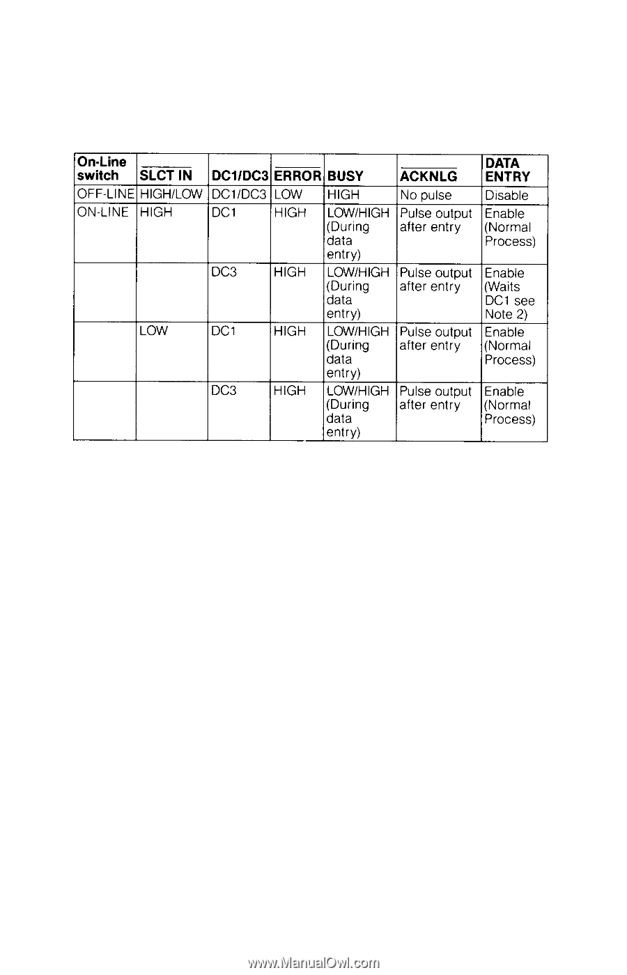
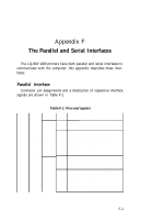
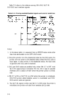
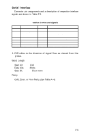
Table F-2 refers to the relations among ON-LINE, SLCT-IN input, DCl/DC3 and interface signals. Table F-2. Printing enabled/disabled signals and control conditions Notes: 1. In the above table, it is assumed that no ERROR status exists other than that attributable to the OFF-LINE mode. 2. Once the printer is in the deselected state by the DC3 code, the printer will not revert to the selected state unless the DC1 code is input again. In other words, in the deselected status, the input data is ignored until DC1 code is received. 3. DC1 and DC3 codes are enabled only when SW 2-7 is OFF. And SLCT-IN signal (Input Connector Pin No. 36 in case of parallel interface unit is used) is HIGH when the printer power is initialized. 4. SW 2-7 is ON or SLCT-IN is LOW when the printer is initialized, DC1/DC3 printer select/deselect control is invalidated and DC1/ DC3 control code are ignored. 5. The SLCT-IN signal is HIGH and SW 2-7 is OFF when the printer is initialized, the printer will start from selected (DC1) state. F-4
-
 1
1 -
2
-
3
-
4
-
5
-
6
-
7
-
8
-
9
-
10
-
11
-
12
-
13
-
14
-
15
-
16
-
17
-
18
-
19
-
20
-
21
-
22
-
23
-
24
-
25
-
26
-
27
-
28
-
29
-
30
-
31
-
32
-
33
-
34
-
35
-
36
-
37
-
38
-
39
-
40
-
41
-
42
-
43
-
44
-
45
-
46
-
47
-
48
-
49
-
50
-
51
-
52
-
53
-
54
-
55
-
56
-
57
-
58
-
59
-
60
-
61
-
62
-
63
-
64
-
65
-
66
-
67
-
68
-
69
-
70
-
71
-
72
-
73
-
74
-
75
-
76
-
77
-
78
-
79
-
80
-
81
-
82
-
83
-
84
-
85
-
86
-
87
-
88
-
89
-
90
-
91
-
92
-
93
-
94
-
95
-
96
-
97
-
98
-
99
-
100
-
101
-
102
-
103
-
104
-
105
-
106
-
107
-
108
-
109
-
110
-
111
-
112
-
113
-
114
-
115
-
116
-
117
-
118
-
119
-
120
-
121
-
122
-
123
-
 124
124 -
 125
125 -
 126
126 -
 127
127 -
 128
128 -
 129
129 -
 130
130 -
 131
131 -
 132
132 -
 133
133 -
 134
134 -
135
-
136
-
137
-
138
-
139
-
140
-
141
-
142
-
143
-
144
-
145
-
146
-
147
-
148
-
149
-
150
-
151
-
152
-
153
-
154
-
155
-
156
-
157
-
158
-
159
-
160
-
161
-
162
-
163
-
164
-
165
-
166
-
167
-
168
-
169
-
170
-
171
-
172
-
173
-
174
-
175
-
176
-
177
-
178
-
179
-
180
-
181
-
182
-
183
-
184
-
185
 |
 |