Epson LQ-1000 User Manual - Page 9
Design grids, Data layout for 24-pin graphics - case
 |
View all Epson LQ-1000 manuals
Add to My Manuals
Save this manual to your list of manuals |
Page 9 highlights
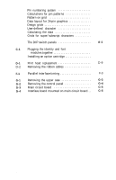
6-1 Pin numbering system 6-4 6-2 Calculations for pin patterns 6-4 6-3 Pattern on grid 6-7 6-4 Data layout for 24-pin graphics 6-8 6-5 Design grids 6-12 6-6 User-defined character 6-13 6-7 Calculating the data 6-14 6-8 Grids for super/subscript characters 6-19 A-1 The DIP switch panels A-1 C-1 Plugging the identity and font modules together C-1 C-2 Installing an option cartridge C-2 D-1 Print head replacement D-9 D-2 Removing the ribbon cables D-10 F-1 Parallel interface timing F-3 G-1 Removing the upper case G-3 G-2 Removing the control panel G-4 G-3 Main circuit board G-5 G-4 Interface board mounted on main circuit board . . G-6 viii
-
 1
1 -
2
-
3
-
 4
4 -
 5
5 -
 6
6 -
 7
7 -
 8
8 -
 9
9 -
 10
10 -
 11
11 -
 12
12 -
 13
13 -
 14
14 -
15
-
16
-
17
-
18
-
19
-
20
-
21
-
22
-
23
-
24
-
25
-
26
-
27
-
28
-
29
-
30
-
31
-
32
-
33
-
34
-
35
-
36
-
37
-
38
-
39
-
40
-
41
-
42
-
43
-
44
-
45
-
46
-
47
-
48
-
49
-
50
-
51
-
52
-
53
-
54
-
55
-
56
-
57
-
58
-
59
-
60
-
61
-
62
-
63
-
64
-
65
-
66
-
67
-
68
-
69
-
70
-
71
-
72
-
73
-
74
-
75
-
76
-
77
-
78
-
79
-
80
-
81
-
82
-
83
-
84
-
85
-
86
-
87
-
88
-
89
-
90
-
91
-
92
-
93
-
94
-
95
-
96
-
97
-
98
-
99
-
100
-
101
-
102
-
103
-
104
-
105
-
106
-
107
-
108
-
109
-
110
-
111
-
112
-
113
-
114
-
115
-
116
-
117
-
118
-
119
-
120
-
121
-
122
-
123
-
124
-
125
-
126
-
127
-
128
-
129
-
130
-
131
-
132
-
133
-
134
-
135
-
136
-
137
-
138
-
139
-
140
-
141
-
142
-
143
-
144
-
145
-
146
-
147
-
148
-
149
-
150
-
151
-
152
-
153
-
154
-
155
-
156
-
157
-
158
-
159
-
160
-
161
-
162
-
163
-
164
-
165
-
166
-
167
-
168
-
169
-
170
-
171
-
172
-
173
-
174
-
175
-
176
-
177
-
178
-
179
-
180
-
181
-
182
-
183
-
184
-
185
 |
 |

6-1
Pin numbering system
......................
6-4
6-2
Calculations for pin patterns
.................
6-4
6-3
Pattern on grid
............................
6-7
6-4
Data layout for 24-pin graphics
...............
6-8
6-5
Design grids
...............................
6-12
6-6
User-defined character
......................
6-13
6-7
Calculating the data
........................
6-14
6-8
Grids for super/subscript characters
...........
6-19
A-1
The DIP switch panels
. . . . . . . . . . . . . . . . . . . . . .
A-1
C-1
C-2
D-1
Print head replacement
......................
D-9
D-2
Removing the ribbon cables
..................
D-10
F-1
Parallel interface timing . . . . . . . . . . . . . . . . . . . . .
F-3
G-1
Removing the upper case
....................
G-3
G-2
Removing the control panel
..................
G-4
G-3
Main circuit board
.........................
G-5
G-4
Interface board mounted on main circuit board . .
G-6
Plugging the identity and font
modules together . . . . . . . . . . . . . . . . . . . . . . . . .
Installing an option cartridge . . . . . . . . . . . . . . . . .
C-1
C-2
viii