Epson LQ-1000 User Manual - Page 136
Altering Serial Interface Settings, printer and computer use compatible protocols.
 |
View all Epson LQ-1000 manuals
Add to My Manuals
Save this manual to your list of manuals |
Page 136 highlights
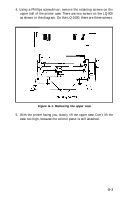
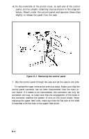
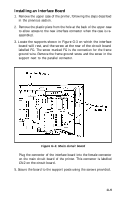
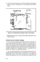
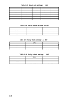
6. Connect the frame ground wire to the FG terminal on the interface board, as shown in the diagram. On the LQ-1000, there are three screws. Figure G-4. Interface board mounted on main circuit board 7. Reassemble the printer, following the procedure described in the previous section. Altering Serial Interface Settings If you are using an optional serial interface, then you may have to alter the communications protocol of the printer or the computer in order to allow them to communicate properly. The protocol used by the printer is decided by one or two groups of DIP switches located on the serial interface board; the protocol used by the computer can probably be altered by a software command. It is essential that the printer and computer use compatible protocols. If you can, adjust the settings on the computer rather than the interface board as the interface is set up at the factory to give optimum performance under a wide range of conditions. If your dealer has installed the interface for you, he or she should also be able to set the G-6
-
 1
1 -
2
-
3
-
4
-
5
-
6
-
7
-
8
-
9
-
10
-
11
-
12
-
13
-
14
-
15
-
16
-
17
-
18
-
19
-
20
-
21
-
22
-
23
-
24
-
25
-
26
-
27
-
28
-
29
-
30
-
31
-
32
-
33
-
34
-
35
-
36
-
37
-
38
-
39
-
40
-
41
-
42
-
43
-
44
-
45
-
46
-
47
-
48
-
49
-
50
-
51
-
52
-
53
-
54
-
55
-
56
-
57
-
58
-
59
-
60
-
61
-
62
-
63
-
64
-
65
-
66
-
67
-
68
-
69
-
70
-
71
-
72
-
73
-
74
-
75
-
76
-
77
-
78
-
79
-
80
-
81
-
82
-
83
-
84
-
85
-
86
-
87
-
88
-
89
-
90
-
91
-
92
-
93
-
94
-
95
-
96
-
97
-
98
-
99
-
100
-
101
-
102
-
103
-
104
-
105
-
106
-
107
-
108
-
109
-
110
-
111
-
112
-
113
-
114
-
115
-
116
-
117
-
118
-
119
-
120
-
121
-
122
-
123
-
124
-
125
-
126
-
127
-
128
-
129
-
130
-
 131
131 -
 132
132 -
 133
133 -
 134
134 -
 135
135 -
 136
136 -
 137
137 -
 138
138 -
 139
139 -
 140
140 -
 141
141 -
142
-
143
-
144
-
145
-
146
-
147
-
148
-
149
-
150
-
151
-
152
-
153
-
154
-
155
-
156
-
157
-
158
-
159
-
160
-
161
-
162
-
163
-
164
-
165
-
166
-
167
-
168
-
169
-
170
-
171
-
172
-
173
-
174
-
175
-
176
-
177
-
178
-
179
-
180
-
181
-
182
-
183
-
184
-
185
 |
 |
