Foxconn P35A-S English manual - Page 25
Jumpers - bios update
 |
View all Foxconn P35A-S manuals
Add to My Manuals
Save this manual to your list of manuals |
Page 25 highlights
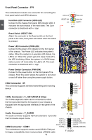
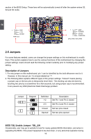
section of the BIOS Setup. These fans will be automatically turned off after the system enters S3, S4 and S5 mode. 2 1 GND +12V SENSE FAN1/2/3 1 GND POWER SENSE CONTROL CPU_FAN / SYS_FAN 2-5 Jumpers For some features needed, users can change the jumper settings on this motherboard to modify them. This section explains how to use the various functions of this motherboard by changing the jumper settings. Users should read the following content carefully prior to modifying any jumper setting. Description of Jumpers 1. For any jumper on this motherboard, pin 1 can be identified by the bold silkscreen next to it. However, in this manual, pin 1 is simply labeled as "1". 2. The following table explains different types of the jumper settings. "Closed" means placing a jumper cap on the two pins to temporarily short them. The shorting can also be done by touching two pins by a screwdriver for a few seconds, but using jumper cap is recommended. It can prevent any ESD (Electrical Static Discharge) problem. Jumper 1 1 Diagram 1 1 1 1 Definition 1-2 2-3 Closed Opened Description Set Pin 1 and Pin 2 closed Set Pin 2 and Pin 3 closed Set two pins closed Set two pins opened BIOS TBL Enable Jumper: TBL_EN Occasionally, user may go to website to look for newly updated BIOS information, and when in upgrading the BIOS, if the power happened to be shut down, or any abnormal operation during 18
-
 1
1 -
2
-
3
-
4
-
5
-
6
-
7
-
8
-
9
-
10
-
11
-
12
-
13
-
14
-
15
-
16
-
17
-
18
-
19
-
 20
20 -
 21
21 -
 22
22 -
 23
23 -
 24
24 -
 25
25 -
 26
26 -
 27
27 -
 28
28 -
 29
29 -
 30
30 -
31
-
32
-
33
-
34
-
35
-
36
-
37
-
38
-
39
-
40
-
41
-
42
-
43
-
44
-
45
-
46
-
47
-
48
-
49
-
50
-
51
-
52
-
53
-
54
-
55
-
56
-
57
-
58
-
59
-
60
-
61
-
62
-
63
-
64
-
65
-
66
-
67
-
68
-
69
-
70
-
71
-
72
-
73
-
74
-
75
-
76
-
77
-
78
-
79
-
80
-
81
-
82
-
83
-
84
-
85
-
86
-
87
-
88
-
89
-
90
-
91
-
92
-
93
-
94
-
95
-
96
-
97
-
98
-
99
-
100
-
101
-
102
-
103
-
104
-
105
-
106
-
107
-
108
-
109
-
110
-
111
-
112
-
113
-
114
-
115
-
116
-
117
 |
 |
