Fujitsu 6010N Getting Started Guide - Page 7
Setting up the Scanner
 |
UPC - 097564307683
View all Fujitsu 6010N manuals
Add to My Manuals
Save this manual to your list of manuals |
Page 7 highlights
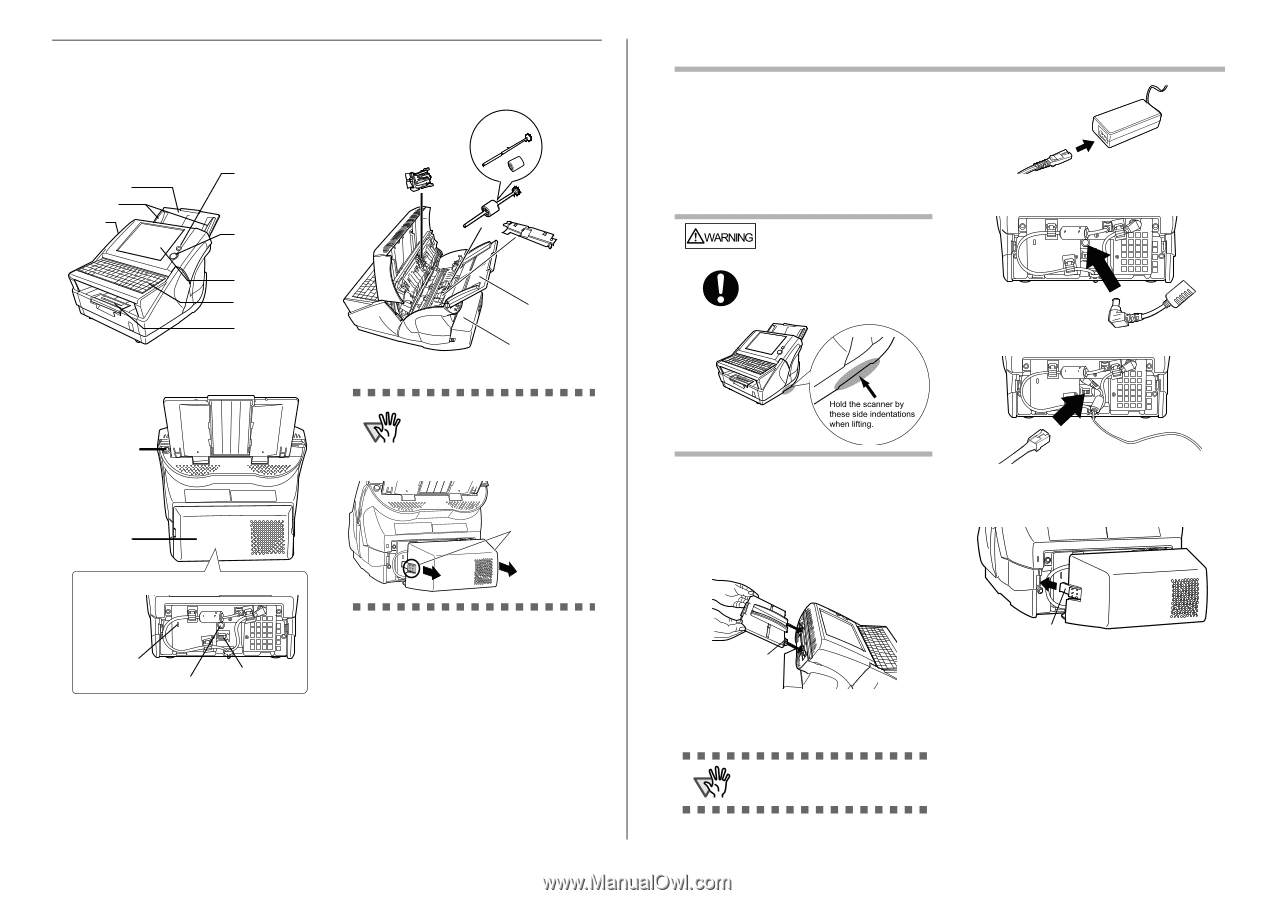
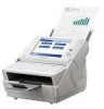
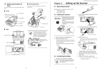
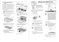
1.5 Names and Functions of Parts This section describes the scanner parts and their functions. ■ Front ADF paper chute Side guides Top cover Startup button [SCAN] button ■ Removable Parts Parts that can be removed from the scanner are displayed below. Pad assembly Separate shaft and roller Pick roller Sheet guide ■ Rear ADF release button Back cover LCD touch panel Keyboard Output tray ADF paper chute Back cover ATTENTION To remove the back cover of the scanner, press the tabs on the cover to unlock it, and pull out. Make sure to pull the cover out straight, to prevent the it from being damaged. Press the tabs on the right and left of the cover and pull out. Inside the back cover Security cable slot LAN connector AC adaptor connector 3 Chapter 2 fi-6010N Network Scanner Getting Started Setting up the Scanner 2.1 Space Requirements The following space is required to set up the scanner: Depth: 700mm (28in) Width: 400mm (16in) Height: 500mm (20in) 2.2 Installing the Scanner WARNING When lifting the scanner, always hold it by the indentations on the bottom of each side to ensure a stable grip. Holding the scanner in any other way may cause it to be dropped or damaged. 2. Connect the AC adapter connector to the scanner's DC inlet. 3. Connect the LAN cable to the LAN connector. Hold the scanner by these side indentations when lifting. 1. Place the scanner at its installation site. 2. Attach the ADF paper chute. Hold the ADF paper chute and insert its tabs into the corresponding slots in the scanner as shown in the following figure. The side guides of the ADF paper chute should face up. 4. Attach the back cover. Attach the cover with the connected AC cable and LAN cable protruding out of the lower part of the cover. Tab 2.3 Connecting the Cables 1. Connect the AC cable to the AC adapter. ATTENTION Use only the AC adapter provided by the manufacturer. Tab To make sure the cover is properly attached, insert the right and left tabs at the same time. 5. Connect the other end of the LAN cable to the network hub. 6. Insert the AC cable into a power outlet. ⇒ The power is connected but the scanner is not yet ready for operation. 4
-
 1
1 -
 2
2 -
 3
3 -
 4
4 -
 5
5 -
 6
6 -
 7
7 -
 8
8 -
 9
9 -
 10
10 -
 11
11 -
 12
12 -
13
-
14
-
15
-
16
-
17
-
18
-
19
-
20
-
21
 |
 |