GE JP389BJBB Use and Care Manual - Page 29
Step I, Step 2, Step 3 - 30 electric
 |
UPC - 084691123736
View all GE JP389BJBB manuals
Add to My Manuals
Save this manual to your list of manuals |
Page 29 highlights
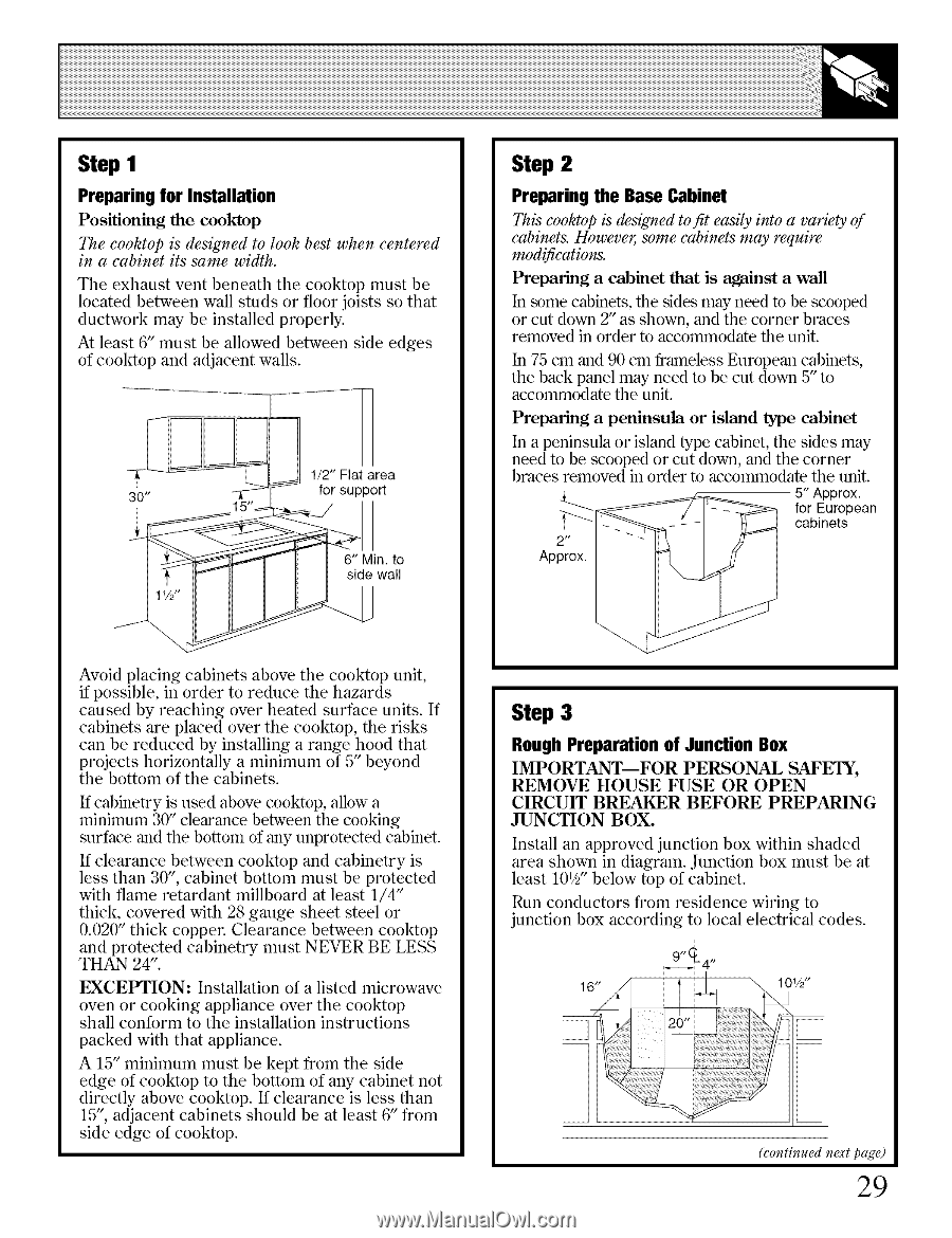
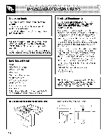
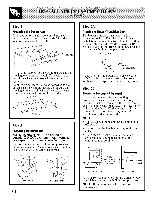
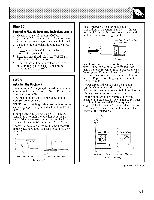
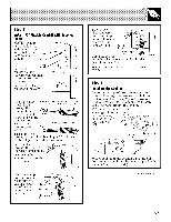
Step I Preparing for Installation Positioning the cooktop The cooktop is designed to look best when centered in a cabinet its same width. The exhaust vent beneath the cooktop must be located between wall studs or floor joists so that ductwork may be installed properly. At least 6" must be allowed between side edges of cooMop and adjacent walls. 1/2" Flat area 30" _ for support 6" Min. to side wall Step 2 Preparing the Base Cabinet This cooktop is designed to fit easily into a variety of cabinets. Howeveg some cabinets may require modifications. Preparing a cabinet that is against a wall In ,some cabinets, the sides may need to be scooped or cut down 2" as shown, and the corner braces removed in order to accommodate the unit. In 75 cm and 90 cm frameless European cabinets, the back panel may need to be cut down 5" to accommodate the unit. Preparing a peninsula or island type cabinet In a peninsula or island type cabinet, the sides may need to be scooped or cut down, and the corner braces removed in order to accommodate the unit. 5" Approx. for European cabinets 2*' Approx. Avoid placing cabinets above the cooktop unit, if possible, in order to reduce the hazards caused by reaching over heated surface units. If cabinets are placed over the cooMop, the risks can be reduced by installing a range hood that projects horizontally a minimum of 5" beyond the bottom of the cabinets. If cabinetry is used above cooktop, allow a minimum 30" clearance between the cooking surface and the bottom of any unprotected cabinet. If clearance between cooktop and cabinetry is less than 30", cabinet bottom must be protected with flame retardant millboard at least 1/4" thick, covered with 28 gauge sheet steel or 0.020" thick copper. Clearance between cooMop and protected cabinetry must NEVER BE LESS THAN 24". EXCEPTION: Installation of a listed microwave oven or cooking appliance over the cooMop shall conform to the installation instructions packed with that appliance. A 15" minimum must be kept from the side edge of cooMop to the bottom of any cabinet not directly above cooMop. If clearance is less than 15% adjacent cabinets should be at least 6" from side edge of cooMop. Step 3 Rough Preparation of Junction Box IMPORTANT--FOR PERSONAL SAFETY, REMOVE HOUSE FUSE OR OPEN CIRCUIT BREAKER BEFORE PREPARING JUNCTION BOX. Install an approved junction box within shaded area shown in diagram. Junction box must be at least 101/2b"elow top of cabinet. Run conductors from residence wiring to junction box according to local electrical codes. (continued next page) 29
-
 1
1 -
2
-
3
-
4
-
5
-
6
-
7
-
8
-
9
-
10
-
11
-
12
-
13
-
14
-
15
-
16
-
17
-
18
-
19
-
20
-
21
-
22
-
23
-
 24
24 -
 25
25 -
 26
26 -
 27
27 -
 28
28 -
 29
29 -
 30
30 -
 31
31 -
 32
32 -
 33
33 -
 34
34 -
35
-
36
-
37
-
38
-
39
-
40
 |
 |