GE JP389BJBB Use and Care Manual - Page 33
conduit., StopTab-I
 |
UPC - 084691123736
View all GE JP389BJBB manuals
Add to My Manuals
Save this manual to your list of manuals |
Page 33 highlights
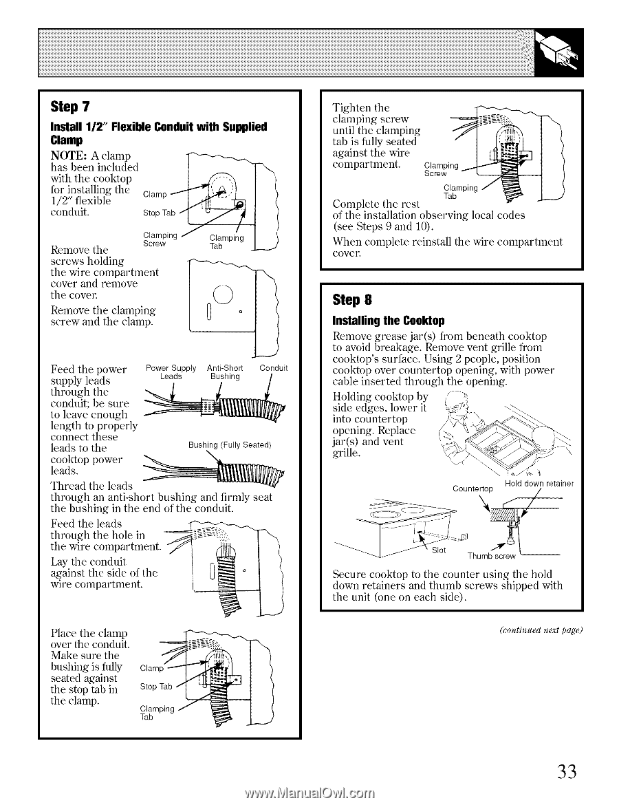
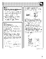
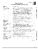
Step 7 Install 112" Flexible Conduit with Supplied Clamp NOTE: A clamp has been included with the cooktop for installing the 1/2" flexible conduit. Remove the Clamp StopTab5-I/'t Clamping J / Clamping Screw Tab screws holding the wire compartment cover and remove the cover. screw and the clamp. Remove the clamping 0 °; Feed the power supply leads Power Supply Anti-Short Conduit Leads Bu/shing tcthoornoldeuaugvihte; etbnheoeusguhre _I'. length to properly connect these leads to the Bushing(FullySeated) leads. cooktop power Thread the leads through an anti-short bushing and firmly seat the bushing in the end of the conduit. Feed the leads through the hole in --__,:, -_ the wire compartment. _'/ ' Lay the conduit In against the side of the I U_ ° wire compartment. _ \ ! Place the clamp over the conduit. Make sure the bushing is fully seated against the stop tab in the clamp. Clamp Stop Tab Clamping Tab Tighten the clamping screw until the clamping tab is fully seated against the wire compartment. Clampin Screw Clamping Tab Complete the rest of the installation observing local (see Steps 9 and 10). codes When complete reinstall the wire compartment cover. Step 8 Installing the Cool(lop Remove grease jar(s) from beneath cooktop to avoid breakage. Remove vent grille from cooktop's surface. Using 2 people, position cooktop over countertop opening, with power cable inserted through the opening. Holding cooMop by side edges, lower it into countertop opening. Replace jar(s) and vent grille. Countertop Hold down retainer _Slot T llu,.nb._c _":_ _ Secure cooktop to the counter using the hold down retainers and thumb screws shipped with the unit (one on each side). (continued next page) 33
-
 1
1 -
2
-
3
-
4
-
5
-
6
-
7
-
8
-
9
-
10
-
11
-
12
-
13
-
14
-
15
-
16
-
17
-
18
-
19
-
20
-
21
-
22
-
23
-
24
-
25
-
26
-
27
-
 28
28 -
 29
29 -
 30
30 -
 31
31 -
 32
32 -
 33
33 -
 34
34 -
 35
35 -
 36
36 -
 37
37 -
 38
38 -
39
-
40
 |
 |