GE JP389BJBB Use and Care Manual - Page 30
Step 4, Step 5A, Step 5B
 |
UPC - 084691123736
View all GE JP389BJBB manuals
Add to My Manuals
Save this manual to your list of manuals |
Page 30 highlights
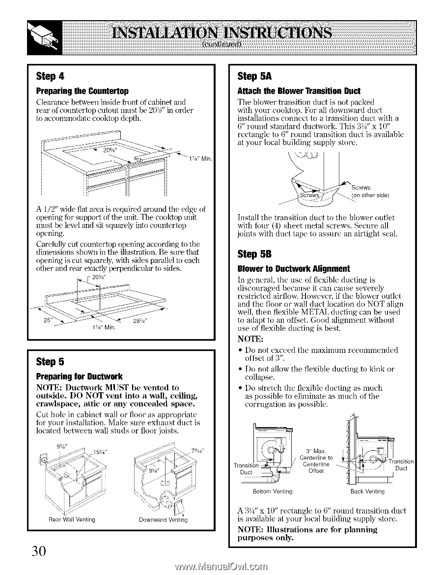
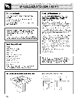
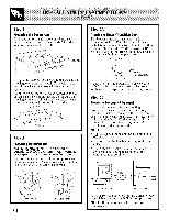
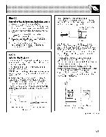
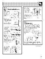
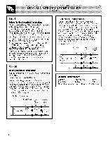
Step 4 Preparing the Countertop Clearance between inside front of cabinet and rear of countertop cutout must be 2@A"in order to accommodate cooktop depth. Min. Step 5A Attach the Blower Transition Duct The blower transition duct is not packed with your cooMop. For all downward duct installations connect to a transition duct with a 6" round standard ductwork. This 31/4"x 10" rectangle to 6" round transition duct is available at your local building supply store. A 1/2" wide flat area is required around the edge of opening for support of the unit. The cooktop unit must be level and sit squarely into countertop opening. Carefully cut countertop opening according to the dimensions shown in the illustration. Be sure that opening is cut squarely, with sides parallel to each other and rear exactly perpendicular to sides. 20%" Step 5 Preparing for Ductwork NOTE: Ductwork MUST be vented to outside. DO NOT vent into a wall, ceiling, crawlspace, attic or any concealed space. Cut hole in cabinet wall or floor as appropriate for your installation. Make sure exhaust duct is located between wall studs or floor joists. /16" Rear Wall Venting 3O Downward Venting _crethe r side) Install the transition duct to the blower outlet with four (4) sheet metal screws. Secure all joints with duct tape to assure an airtight seal. Step 5B Blower to Ductwork Alignment In general, the use of flexible ducting is discouraged because it can cause severely restricted airflow. However, if the blower outlet and the floor or wall duct location do NOT align well, then flexible METAL ducting can be used to adapt to an offset. Good alignment without use of flexible ducting is best. NOTE: • Do not exceed the maximum recommended offset of 3". • Do not allow the flexible ducting to kink or collapse. • Do stretch the flexible ducting as much as possible to eliminate as much of the corrugation as possible. =g Transiti 3" Max. Centerline to Centerline Duct ©ffset _ _Transition Bottom Venting Back Venting A 31/4"x 10" rectangle to 6" round transition duct is available at your local building supply store. NOTE: Illustrations are for planning purposes only.
-
 1
1 -
2
-
3
-
4
-
5
-
6
-
7
-
8
-
9
-
10
-
11
-
12
-
13
-
14
-
15
-
16
-
17
-
18
-
19
-
20
-
21
-
22
-
23
-
24
-
 25
25 -
 26
26 -
 27
27 -
 28
28 -
 29
29 -
 30
30 -
 31
31 -
 32
32 -
 33
33 -
 34
34 -
 35
35 -
36
-
37
-
38
-
39
-
40
 |
 |