Gigabyte GA-6QPCV-RH Manual
Gigabyte GA-6QPCV-RH Manual
 |
View all Gigabyte GA-6QPCV-RH manuals
Add to My Manuals
Save this manual to your list of manuals |
Gigabyte GA-6QPCV-RH manual content summary:
- Gigabyte GA-6QPCV-RH | Manual - Page 1
GA-6QPCV-RH Intel® mini-ITX Motherboard USER'S MANUAL Intel® mini-ITX Motherboard Rev. 1001 * The WEEE marking on the product indicates this product must not be disposed of with user's other household waste - Gigabyte GA-6QPCV-RH | Manual - Page 2
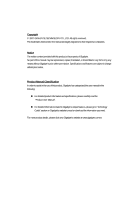
: For detailed product information and specifications, please carefully read the "Product User Manual". For detailed information related to Gigabyte's unique features, please go to "Technology Guide" section on Gigabyte's website to read or download the information you need. For more product details - Gigabyte GA-6QPCV-RH | Manual - Page 3
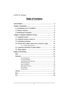
GA-6QPCV-RH Motherboard Table of Contents Item Checklist 4 Chapter 1 Introduction 5 1-1 Considerations Prior to Installation 5 1.2 Features Summary 8 1.3 Motherboard Components 10 Chapter 2 Hardware Installation Process 11 2-1: Installing Processor 11 2-2: - Gigabyte GA-6QPCV-RH | Manual - Page 4
Item Checklist The GA-6QPCV-RH motherboard Serial ATA cable x 2 I/O Shield Kit HDD Power (SATA & 4P) cable x 2 CD for motherboard driver & utility GA-6QPCV-RH Quick Reference Guide Introduction * The items listed above are for reference only, and are subject to change without notice. 4 - Gigabyte GA-6QPCV-RH | Manual - Page 5
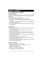
GA-6QPCV-RH installation, please follow the instructions below: 1. Please turn off the information in the provided manual. 3. Before using the about any installation steps or have a problem related to the use of the product, the conditions recommended in the user manual. 3. Damage due to improper - Gigabyte GA-6QPCV-RH | Manual - Page 6
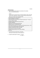
begin Intel® AMT & Intel® TPM testing Install OS 2. Recommanded CPU Cooler APR Vender: Cooler Master Vender cooler P/N:GECC-00633-01-GP/ECC-00633-01-GP 3. GA-6QPCV-RH 90W Adpater Max Support I. 2.5" HDD *4 II. 3.5" HDD * 2 6 - Gigabyte GA-6QPCV-RH | Manual - Page 7
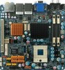
GA-6QPCV-RH Motherboard 4. Suggested to blow the wind generated by system fan to the DC convertor near CPU. (Please see the marked location below:) 7 - Gigabyte GA-6QPCV-RH | Manual - Page 8
CPU y 170mm x 170mm Mini ITX form factor, 8 layers PCB. y Supports single Intel® Merom/Penryn/Celeron M585/M575 Chipset Memory I/O Control Expansion Slots SATA Controller On-Board Graphic Internal Connector Rear Panel I/O series processor y Socket P with - Gigabyte GA-6QPCV-RH | Manual - Page 9
GA-6QPCV-RH Motherboard y y On-Board LAN y y BIOS y Additional Features y y y y y values viewing CPU/Power/System Fan Revolution Detect CPU shutdown when overheat Intel® 82567LM and 82574L GbE controllers Supports WOL, PXE Phoenix BIOS on 16Mb x 2 SPI Flash ROM External Modem wake up - Gigabyte GA-6QPCV-RH | Manual - Page 10
1.3 Motherboard Components PS/2 HDMI Introduction DC Power Jack Audio USB USB jack & & VGA LAN LAN F_Audio LVDS_CTL1 Intel Intel 82567LM 82574L SPDIF YPbPr Intel ICH9M-E Intel GM45 DDR 1 DDR 2 LVDS (Master) LVDS (Slave) PCI 32/33MHz SYS_FAN COM1 COM2 Mini PCI-E ITE - Gigabyte GA-6QPCV-RH | Manual - Page 11
GA-6QPCV-RH Motherboard Chapter 2 Hardware Installation Process 2-1: Installing Processor Step 1 Step 2 The processor socket come with a screw to secure the processor. Insert the CPU into the socket - Gigabyte GA-6QPCV-RH | Manual - Page 12
2-2: Installing Processor Colling Fan Hardware Installation Process WARNING! ! To prevent the CPU overheat, please make sure you have apply the CPU cooler paste on the surface of installed CPU Step 1 Attach the heat sink n the procssor socket. Secure the cooing fan with screws. Step 2 Connect - Gigabyte GA-6QPCV-RH | Manual - Page 13
GA-6QPCV-RH Motherboard 2-3: Install Memory Modules Before installing the memory modules, please comply with the following conditions: 1. Please make sure the computer power is switched off before installing or removing memory modules. The motherboard supports DDR2 memory module, whereby BIOS will - Gigabyte GA-6QPCV-RH | Manual - Page 14
Table 1. Supported DIMM Module Type Size 512MB 1GB 2GB Organization 16MB x 8 x 8bks 32MB x 16 x 8bks 32MB x 8 x 8bks 64MB x 16 x 8bks 32MB x 8 x 8bks 64MB x 16 x 8bks Hardware Installation Process RAM Chips/DIMM 8 16 8 16 8 16 14 - Gigabyte GA-6QPCV-RH | Manual - Page 15
GA-6QPCV-RH Motherboard 2-4: Connect ribbon cables, cabinet wires, and power supply 2-4-1 : I/O Back Panel Introduction 15 - Gigabyte GA-6QPCV-RH | Manual - Page 16
.), and enter BIOS Setup, then set Onboard VGA output connect to D-SUB/ HDMI under Advanced BIOS Features. Please note the HDMI audio output only supports AC3, DTS and 2-channel-LPCM formats. (AC3 and DTS require the use of an external decoder for decoding.) In Windows XP, select Start>Control - Gigabyte GA-6QPCV-RH | Manual - Page 17
GA-6QPCV-RH Motherboard In Windows Vista, select Start>Control Panel>Sound, select Realtek HDMI Output and then click Set Default. PS/2 Keyboard and PS/2 Mouse Connector This - Gigabyte GA-6QPCV-RH | Manual - Page 18
device(s) such as USB keyboard, mouse, scanner, zip, speaker...etc. have a standard USB interface. Also make sure your OS supports USB controller. If your OS does not support USB controller, please contact OS vendor for possible patch or driver updated. For more information please contact your OS or - Gigabyte GA-6QPCV-RH | Manual - Page 19
GA-6QPCV-RH Motherboard LAN LED Description LED2 (Green/Yellow) LED1 (Green) Name LED1 LED2 Color Green Green Green Green Yellow Yellow Condition ON BLINK OFF OFF OFF - Gigabyte GA-6QPCV-RH | Manual - Page 20
Connector Introduction 2-5: Connectors Introduction & Jumper Setting 20 23 18 24 25 5 21 6 22 10 11 26 13 14 3 74 2 1 15 89 12 16 17 19 1. SATA1 (SATA cable connector) 14. PWR1 2. SATA2 (SATA cable connector) 15. PWR2 3. SATA3 (SATA cable connector) 16. F_Panel (Front Panel - Gigabyte GA-6QPCV-RH | Manual - Page 21
GA-6QPCV-RH Motherboard 1/ 2/ 3/ 4 ) SATA 1~4 (Serial ATA cable connectors) SATA 3Gb/s can provide up to 300MB/s stransfer rate. Please refer to the BIOS setting for the SATA 3Gb/s - Gigabyte GA-6QPCV-RH | Manual - Page 22
Connector Introduction 7/ 8/ 9 ) F_USB1/2/3 (Front USB cable connectors) Be careful with the polarity of the front USB connector. Check the pin assignment carefully while you connect the front USB cable, incorrect connection between the cable and connector will make the device unable to work or even - Gigabyte GA-6QPCV-RH | Manual - Page 23
GA-6QPCV-RH Motherboard 10/ 11) LVDS connectors (Master/Slave) LVDS stands for Low-voltage differential signaling, which uses high-speed analog circuit techniques to provide multigigabit data - Gigabyte GA-6QPCV-RH | Manual - Page 24
connector and possesses a foolproof connection design. Most coolers are designed with color-coded power connector wires. A red power connector wire indicates a positive connection and requires a +12V power voltage. The black connector wire is the ground wire (GND). Remember to connect the CPU/system - Gigabyte GA-6QPCV-RH | Manual - Page 25
GA-6QPCV-RH Motherboard 16 ) F_Panel (2X10 Pins Front Panel connector) Please connect the power LED, PC speaker, reset switch and power switch of your chassis front panel - Gigabyte GA-6QPCV-RH | Manual - Page 26
17) WLAN_LED1 (Wireless LAN LED connector) Connector Introduction Pin No. Definition 1 WLAN_LED+ 2 WLAN_LED- 1 18) LVDS_CTL1 (LVDS panel control connector) Pin No. Definition 1 LBKLT_EN 2 GND 3 LBKLT_CTRL 6 1 4 PANEL_BKLT 5 PANEL_BKLT 6 P5V 26 - Gigabyte GA-6QPCV-RH | Manual - Page 27
GA-6QPCV-RH Motherboard 19 ) BAT1 (Battery) CAUTION Danger of explosion if battery is incorrectly replaced. Replace only with the same or equivalent type recommended by the manufacturer. Dispose of used batteries according to the manufacturer's instructions are buying support front audio connector - Gigabyte GA-6QPCV-RH | Manual - Page 28
21/22 ) COMS2/COMS1 (Power COM selection jumper) Jumper Setting COMS1 COMS2 51 1-2 Close: RI (STAND COM) 62 51 3-4 Close: 5V (Power COM) 62 51 5-6 Close: 12V (Power COM) 62 28 - Gigabyte GA-6QPCV-RH | Manual - Page 29
GA-6QPCV-RH Motherboard 23 ) LVDS_PSEL2 (LVDS power source selection jumper) 1 1-2 Close: 5V 1 2-3 Close:3.3V (Default setting) 29 - Gigabyte GA-6QPCV-RH | Manual - Page 30
24 ) CLR_ME1 (ME clear jumper) Jumper Setting Open: Normal operation. (Default setting) Close: Clear ME data. 30 - Gigabyte GA-6QPCV-RH | Manual - Page 31
GA-6QPCV-RH Motherboard 25 ) BIOS_RE1 (BIOS recovery jumper) Open: Normal operation. (Default setting) Close: Enable BIOS recovery function. 31 - Gigabyte GA-6QPCV-RH | Manual - Page 32
Jumper Setting 26 ) CLR_CMOS1 (Clear CMOS Function) You may clear the CMOS data to restore its default values by this jumper. Default value doesn't include the "Shunter" to prevent from improper use this jumper. To clear CMOS, temporarily short 1-2 pin. 1 1-2 Close: Clear CMOS 1 2-3 Close: Normal - Gigabyte GA-6QPCV-RH | Manual - Page 33
2-6: Block Diagram VGA Connector CPU Intel Merom Clock Generator ICS ICS9LP505 Block Diagram PCI 32/33MHz slot Pb Pr HDMI HOST BUS SPDIF Y TV Out NB RJ45 RJ45 Intel GM45 USB2 USB0 USB3 USB1 LVDS LAN LAN DMI Inel Inel 82547L 82567LM GLCI/LCI BUS PCI-E BUS PCI BUS SB Intel HD - Gigabyte GA-6QPCV-RH | Manual - Page 34
Chapter 3 BIOS Setup BIOS Setup BIOS (Basic Input and Output System) includes a CMOS SETUP utility which allows user to configure required settings or to activate certain system features. The CMOS SETUP saves the configuration in the CMOS SRAM of the motherboard. When the power is turned off, the - Gigabyte GA-6QPCV-RH | Manual - Page 35
GA-6QPCV-RH Motherboard GETTINGHELP Main Menu The on-line description of the highlighted setup function is displayed at the bottom of the screen. Status Page Setup Menu / - Gigabyte GA-6QPCV-RH | Manual - Page 36
Main BIOS Setup Once you enter Phoenix BIOS Setup Utility, the Main Menu (Figure 1) will appear on the screen. Use arrow keys to select among the items and press to accept or enter the sub-menu. Figure 1: Main System Time The time is calculated based on the 24-hour military time clock. - Gigabyte GA-6QPCV-RH | Manual - Page 37
GA-6QPCV-RH Motherboard IDE Channel 0 Master/Slave/SATA Port 1/2/3/4 The category identifies the occurs multiple sectors at a time if the device supports it. LBA Mode 32-Bit I/O This field shows if the device type in the specific IDE channel support LBA Mode. Enable this function to max imize the - Gigabyte GA-6QPCV-RH | Manual - Page 38
installed BIOS Setup Halt On The category determines whether the computer will stop if an error is detected during power up. No Errors The system boot will not stop for any error that may be detected and you will be prompted. All, But Keyboard The system boot will not stop for a keyboard - Gigabyte GA-6QPCV-RH | Manual - Page 39
GA-6QPCV-RH Motherboard Advanced About This Section: Advanced With this section, allowing user to configure your system for advanced operation. User can set the CPU Features, GM965 Features, ICH8MD0 Features, Super I/O Features, Power Features and Hardware Monitor Features. Figure 2: Advanced 39 - Gigabyte GA-6QPCV-RH | Manual - Page 40
System Management BIOS Setup Figure 2-1: System Information System Management This category includes the information of BIOS Version, Product Name, BIOS Build Date, CPU Type, CPU Speed, Memory DIMM1/ DIMM2, LAN1/LAN2 MAC Address, and GBIA Module Version. 40 - Gigabyte GA-6QPCV-RH | Manual - Page 41
GA-6QPCV-RH Motherboard CPU Control Sub-Menu Figure 2-2: CPU Control Sub-Menu Manufacturer This item displays the information of original CPU manufacturer. CPU Type This item displays - Gigabyte GA-6QPCV-RH | Manual - Page 42
Intel (R) SpeedStep (tm) BIOS Setup Intel SpeedStep technology allows the system to dynamically adjust processor voltage and core frequency, which can result in decreased average power consumption and decreased average heat production. Enabled Enable Intel SpeedStep function. (Default setting) - Gigabyte GA-6QPCV-RH | Manual - Page 43
GA-6QPCV-RH Motherboard Video (Intel IGD) Control Sub-Menu Figure 2-3: Video (Intel IGD) Control Sub-Menu IGDDevice 2 Enable or disable the Internal Graphics Device by setting this - Gigabyte GA-6QPCV-RH | Manual - Page 44
BIOS Setup IGD - LCD Control Sub-Menu IGD -LCD Panel Type Select the LCD Panel used by the Internal Graphics Device by selecting the appropriate setup item. The first item is Panel 1, the last item is Panel 16. Some Panels are not numbered due to size constraints. Options 648x480 LVDS, 800x600 - Gigabyte GA-6QPCV-RH | Manual - Page 45
GA-6QPCV-RH Motherboard Total Graphics Memory The POST of the BIOS will determine the amount of total graphics memory detected in the system. Render Standby Enabled Enlable Render Standby support. (Default setting) Disabled Disable Render Standby support. 45 - Gigabyte GA-6QPCV-RH | Manual - Page 46
ICH Control Sub-Menu BIOS Setup Figure 2-4: ICH Control Sub-Menu Legacy USB Support Enabled Enable support for Legacy Universal Serial bus. Disabled Disable support for Legacy Universal Serial bus. SATA Mode Selection Determine the SATA mode operation. IDE Set the SATA mode to IDE. (Default - Gigabyte GA-6QPCV-RH | Manual - Page 47
GA-6QPCV-RH Motherboard Enabled Azalia device will unconditionally enabled. Disabled Disable Azalia device. Init Display First This feature allows you to select the first initation of the - Gigabyte GA-6QPCV-RH | Manual - Page 48
Super I/O Sub-Menu BIOS Setup Figure 2-5: Super I/O Sub-Menu Serial Port A This allows users to configure serial prot A by using this option. Enabled Disabled Enable the configuration (Default setting) Disable the configuration. Base I/O address 3F8/IRQ4 Set IO address to 3F8/IRQ4. (Default - Gigabyte GA-6QPCV-RH | Manual - Page 49
GA-6QPCV-RH Motherboard Serial Port B This allows users to configure serial prot B by using this option. Enabled Disabled Enable the configuration (Default setting) Disable the configuration. Base I/O - Gigabyte GA-6QPCV-RH | Manual - Page 50
Power Feature Sub-Menu BIOS Setup Figure 2-6: Power Feature Sub-Menu Disable ACPI Sx Set the ACPI power state for your system. None Disable this function. (Default setting) S1 Set ACPI suspend type to S1 (Power On Suspend). S3 Set ACPI suspend type to S3(Suspend To RAM). Soft-Off by PWR - Gigabyte GA-6QPCV-RH | Manual - Page 51
GA-6QPCV-RH Motherboard Power On System power state when AC cord is re-plugged. Wake Up by LAN/PME Enabled Enable LAN/PME as wake up function. ( - Gigabyte GA-6QPCV-RH | Manual - Page 52
AMT Sub-Menu BIOS Setup Figure 2-7: AMT Sub-Menu Intel AMT Enabled Enable Intel AMT Active Management Technology BIOS Extension. (Default setting) Disabled Disable Intel AMT Active Management Technology BIOS Extension. Platform Manageability This item can not be adjusted, displays only. Watch - Gigabyte GA-6QPCV-RH | Manual - Page 53
GA-6QPCV-RH Motherboard BIOS Timer Config. Press "+" to configure the desired value of BIOS ME IDE Redirection support. (Default setting) Disabled Disable ME IDE Redirection support. ME KT Enabled Enable ME KT support. (Default setting) Disabled Disable ME KT support. Console Redirection - Gigabyte GA-6QPCV-RH | Manual - Page 54
BIOS Setup Continue C.R. after POST This option allows user to enable console redirection after O.S has loaded. On Enable console redirection after O.S has loaded. (Default setting) Off Disable this function. 54 - Gigabyte GA-6QPCV-RH | Manual - Page 55
GA-6QPCV-RH Motherboard Hardware Monitor Figure 2-8: Hardware Monitor CPU Temperature/System Temperature Detects and displays current system and CPU temperature automatically. Fan Monitor Detects and displays the - Gigabyte GA-6QPCV-RH | Manual - Page 56
BIOS Setup Quick Boot Mode Set this item to enable will allow to skip sertain tests suring booting. This will decrease the time needed to boot the system. Enabled Enable Quick Boot Mode. (Default setting) Disabled Disable Quick Boot Mode. Boot-time Diagnostic Screen When this item is enabled, system - Gigabyte GA-6QPCV-RH | Manual - Page 57
GA-6QPCV-RH Motherboard Security About This Section: Security In this section, user can set either supervisor or user passwords, or both for different level of password securities. - Gigabyte GA-6QPCV-RH | Manual - Page 58
that this item will be adjustable when supervision password is set. Enabled Requries entering password when system on boot. Disabled TPM Support Disable this function. (Default setting) TPM, stands for Trusted Platform Module. A Trusted Platform Module provides function for secure generation of - Gigabyte GA-6QPCV-RH | Manual - Page 59
GA-6QPCV-RH Motherboard Boot Figure 4: Boot Boot Priority Order This field determines which type of device the system attempt to boot from after PhoenixBIOS Post completed. Specifies - Gigabyte GA-6QPCV-RH | Manual - Page 60
Exit BIOS Setup Figure 5: Exit About This Section: Exit Once you have changed all of the set values in the BIOS setup menu, you should save your changes and exit BIOS setup program. Select "Exit" from the menu bar, to display the following sub-menu. Exit Saving Changes Exit Discarding Changes Load - Gigabyte GA-6QPCV-RH | Manual - Page 61
GA-6QPCV-RH Motherboard Exit Saving Changes This option allows user to exit system setup with saving the changes. Press on this item to ask for the - Gigabyte GA-6QPCV-RH | Manual - Page 62
BIOS Setup Exit Discarding Changes This option allows user to exit system setup without changing any previous settings values in CMOS. The previous selection remain in effect. This will exit the Setup Utility and restart your compuetr when selecting this option. 62 - Gigabyte GA-6QPCV-RH | Manual - Page 63
GA-6QPCV-RH Motherboard &Load Setup Default This option allows user to load default values for all setup items. When you press on this item, you will get a confirmation dialog box with a message as below: 63 - Gigabyte GA-6QPCV-RH | Manual - Page 64
BIOS Setup Discard Changes This option allows user to load previos values from CMOS for all setup item. When you press on this item, you will get a confirmation dialog box with a message as below: 64 - Gigabyte GA-6QPCV-RH | Manual - Page 65
GA-6QPCV-RH Motherboard Save Changes This option allows user to save setup dat ato CMOS. When you press on this item, you will get a confirmation dialog box with a message as below: Press [Yes] to save setup daya to CMOS. 65
-
 1
1 -
 2
2 -
 3
3 -
 4
4 -
 5
5 -
 6
6 -
 7
7 -
8
-
9
-
10
-
11
-
12
-
13
-
14
-
15
-
16
-
17
-
18
-
19
-
20
-
21
-
22
-
23
-
24
-
25
-
26
-
27
-
28
-
29
-
30
-
31
-
32
-
33
-
34
-
35
-
36
-
37
-
38
-
39
-
40
-
41
-
42
-
43
-
44
-
45
-
46
-
47
-
48
-
49
-
50
-
51
-
52
-
53
-
54
-
55
-
56
-
57
-
58
-
59
-
60
-
61
-
62
-
63
-
64
-
65
 |
 |

USER’S MANUAL
GA-6QPCV-RH
Intel
®
mini-ITX Motherboard
Intel
®
mini-ITX Motherboard
Rev. 1001
*
The WEEE marking on the product indicates this product must not be disposed of with
user's other household waste and must be handed over to a designated collection point
for the recycling of waste electrical and electronic equipment!!
*
The WEEE marking applies only in European Union's member states.