Gigabyte GA-6QPCV-RH Manual - Page 25
F_Panel, 2X10 Pins Front Panel connector
 |
View all Gigabyte GA-6QPCV-RH manuals
Add to My Manuals
Save this manual to your list of manuals |
Page 25 highlights
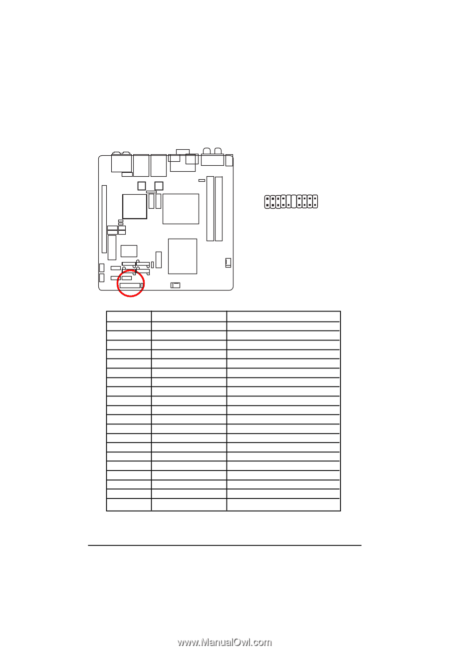
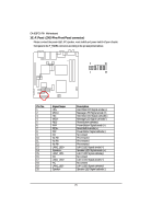
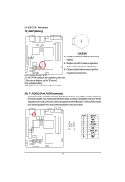
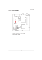
GA-6QPCV-RH Motherboard 16 ) F_Panel (2X10 Pins Front Panel connector) Please connect the power LED, PC speaker, reset switch and power switch of your chassis front panel to the F_PANEL connector according to the pin assignment above. 2 20 1 19 Pin No. 1. 2. 3. 4. 5. 6. 7. 8. 9. 10. 11. 12. 13. 14. 15. 16. 17. 18. 19. 20. Signal Name HD+ MSG+ HDMSGRESPW+ RES+ PWNC No Pin No Pin No Pin LAN2_LED+ Speaker+ LAN2_LEDNC LAN1_LED+ NC LAN1_LEDSpeaker- Description Hard Disk LED Signal anode (+) Message LED Signal anode (+) Hard Disk LED Signal cathode(-) Message LED Signal cathode(-) Reset Button cathode(-) Power Button Signal anode (+) Reset Button anode (+) Power Button Signal cathode(-) No connect Pin removed Pin removed Pin removed LAN 2 LED Signal anode (+) Speaker LED Signal anode (+) LAN 2 LED Signal cathode(-) No connect LAN 1 LED Signal anode (+) No connect LAN 1 LED Signal cathode(-) Speaker LED Signal cathode(-) 25
-
 1
1 -
2
-
3
-
4
-
5
-
6
-
7
-
8
-
9
-
10
-
11
-
12
-
13
-
14
-
15
-
16
-
17
-
18
-
19
-
 20
20 -
 21
21 -
 22
22 -
 23
23 -
 24
24 -
 25
25 -
 26
26 -
 27
27 -
 28
28 -
 29
29 -
 30
30 -
31
-
32
-
33
-
34
-
35
-
36
-
37
-
38
-
39
-
40
-
41
-
42
-
43
-
44
-
45
-
46
-
47
-
48
-
49
-
50
-
51
-
52
-
53
-
54
-
55
-
56
-
57
-
58
-
59
-
60
-
61
-
62
-
63
-
64
-
65
 |
 |