Gigabyte GA-6QPCV-RH Manual - Page 24
CPU_FAN1/SYS_FAN1, fan/System fan cable connectors, 15 PWR1/2 Power Output connectors - positive
 |
View all Gigabyte GA-6QPCV-RH manuals
Add to My Manuals
Save this manual to your list of manuals |
Page 24 highlights
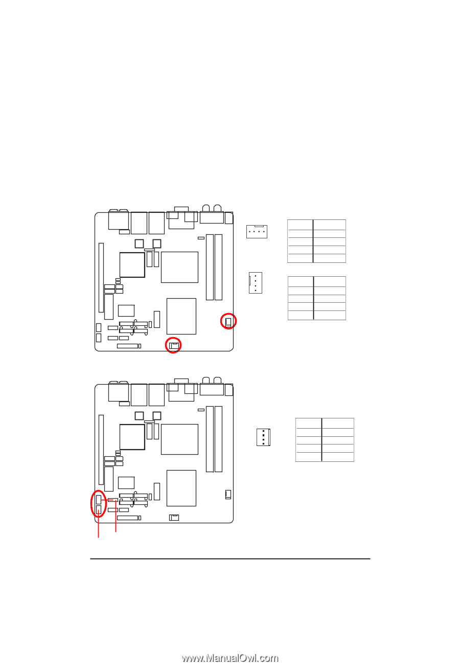
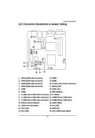
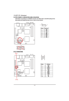
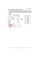
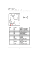
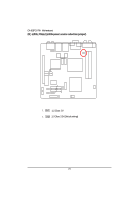
Connector Introduction 12/ 13 ) CPU_FAN1/SYS_FAN1 (CPU fan/System fan cable connectors) The cooler fan power connector supplies a +12V power voltage via a 3-pin/4-pin(CPU_FAN) power connector and possesses a foolproof connection design. Most coolers are designed with color-coded power connector wires. A red power connector wire indicates a positive connection and requires a +12V power voltage. The black connector wire is the ground wire (GND). Remember to connect the CPU/system fan cable to the CPU_FAN/SYS_FAN connector to prevent CPU damage or system hanging caused by overheating. 4 1 1 4 SYS_FAN1 Pin No. 1 2 3 4 Definition GND 12V Sense Control Pin No. 1 2 3 4 Definition GND 12V Sense Control CPU_FAN1 14/ 15 ) PWR1/2 (Power Output connectors) 1 Pin No. Definition 1 12V 2 GND 3 GND 4 4 5V PWR1 PWR2 24
-
 1
1 -
2
-
3
-
4
-
5
-
6
-
7
-
8
-
9
-
10
-
11
-
12
-
13
-
14
-
15
-
16
-
17
-
18
-
 19
19 -
 20
20 -
 21
21 -
 22
22 -
 23
23 -
 24
24 -
 25
25 -
 26
26 -
 27
27 -
 28
28 -
 29
29 -
30
-
31
-
32
-
33
-
34
-
35
-
36
-
37
-
38
-
39
-
40
-
41
-
42
-
43
-
44
-
45
-
46
-
47
-
48
-
49
-
50
-
51
-
52
-
53
-
54
-
55
-
56
-
57
-
58
-
59
-
60
-
61
-
62
-
63
-
64
-
65
 |
 |