Gigabyte GA-6UASL1 Manual - Page 16
Internal Connectors
 |
View all Gigabyte GA-6UASL1 manuals
Add to My Manuals
Save this manual to your list of manuals |
Page 16 highlights
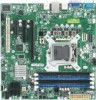
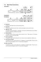
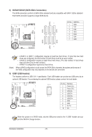
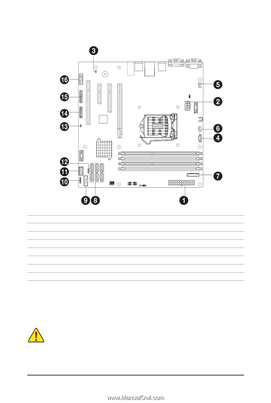
1-6 Internal Connectors 1) P1 2) P2_CPU1 3) CASE_OPEN1 4) PWR_DET1 5) FAN4 (System Fan) 6) FAN1 (CPU Fan) 7) BAT1 8) SATA0/1/2/3/4/5 9) USB1 10) USB2 11) USB_A1 12) SGPIO1 13) HD_LED1 14) F_PANEL2 15) TPM_1 16) COM2 Read the following guidelines before connecting external devices: • First make sure your devices are compliant with the connectors you wish to connect. • Before installing the devices, be sure to turn off the devices and your computer. Unplug the power cord from the power outlet to prevent damage to the devices. • After installing the device and before turning on the computer, make sure the device cable has been securely attached to the connector on the motherboard. - 16 - Hardware Installation
-
 1
1 -
2
-
3
-
4
-
5
-
6
-
7
-
8
-
9
-
10
-
 11
11 -
 12
12 -
 13
13 -
 14
14 -
 15
15 -
 16
16 -
 17
17 -
 18
18 -
 19
19 -
 20
20 -
 21
21 -
22
-
23
-
24
-
25
-
26
-
27
-
28
-
29
-
30
-
31
-
32
-
33
-
34
-
35
-
36
-
37
-
38
-
39
-
40
-
41
-
42
-
43
-
44
-
45
-
46
-
47
-
48
-
49
-
50
-
51
-
52
-
53
-
54
-
55
-
56
-
57
-
58
-
59
 |
 |
- 16 -
Hardware Installation
1-6
Internal Connectors
Read the following guidelines before connecting external devices:
•
First make sure your devices are compliant with the connectors you wish to connect.
•
Before installing the devices, be sure to turn off the devices and your computer. Unplug the
power cord from the power outlet to prevent damage to the devices.
•
After installing the device and before turning on the computer, make sure the device cable has
been securely attached to the connector on the motherboard.
1)
P1
2)
P2_CPU1
3)
CASE_OPEN1
4)
PWR_DET1
5)
FAN4 (System Fan)
6)
FAN1 (CPU Fan)
7)
BAT1
8)
SATA0/1/2/3/4/5
9)
USB1
10)
USB2
11)
USB_A1
12)
SGPIO1
13)
HD_LED1
14)
F_PANEL2
15)
TPM_1
16)
COM2