Gigabyte GA-6UASL1 Manual - Page 6
Type A USB connector
 |
View all Gigabyte GA-6UASL1 manuals
Add to My Manuals
Save this manual to your list of manuals |
Page 6 highlights
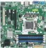
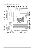
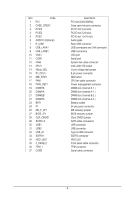
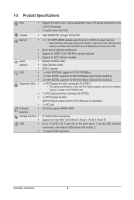
Item Code 1 PCI 2 CASE_OPEN1 3 PCIE3 4 PCIE2 5 PCIE1 6 AUDIO1 (Optional) 7 R_USB1 8 USB_LANA1 9 USB_LANB1 10 VGA1 11 COM1 12 FAN4 13 CPU1 14 VBoot_SEL 15 P2_CPU1 16 NMI_BTN1 17 FAN1 18 PWR_DET1 19 DIMM1B 20 DIMM1A 21 DIMM2B 22 DIMM2A 23 BAT1 24 P1 25 ME_F_JP1 27 BIOS_JP1 28 CLR_CMOS1 29 SATA0~5 30 USB1 31 USB2 32 USB_A1 33 SGPIO1 34 HDD_LED1 35 F_PANEL2 36 TPM_1 37 COM2 Description PCI slot (32bit/33MHz) Case open intrusion connector PCI-E slot 3 (x4 slot) PCI-E slot 2 (x8 slot) PCI-E slot 1 (x16 slot) Audio jacks Rear USB connector USB connectors and LAN connector USB connectors VGA port Serial port System fan cable connector Intel LGA1155 socket Vcore voltage test jumper 8 pin power connector NMI button CPU fan cable connector Power management connector DIMM slot (channel B-1 ) DIMM slot (channel A-1 ) DIMM slot (channel B-2 ) DIMM slot (channel A-2 ) Battery socket 24 pin power connector ME recovery jumper BIOS recovery jumper Clear CMOS jumper SATA cable connectors USB connector USB connector Type A USB connector SGPIO connector HDD LED Front panel cable connector TPM connector Serial cable connector - 6 -
-
 1
1 -
 2
2 -
 3
3 -
 4
4 -
 5
5 -
 6
6 -
 7
7 -
 8
8 -
 9
9 -
 10
10 -
 11
11 -
 12
12 -
13
-
14
-
15
-
16
-
17
-
18
-
19
-
20
-
21
-
22
-
23
-
24
-
25
-
26
-
27
-
28
-
29
-
30
-
31
-
32
-
33
-
34
-
35
-
36
-
37
-
38
-
39
-
40
-
41
-
42
-
43
-
44
-
45
-
46
-
47
-
48
-
49
-
50
-
51
-
52
-
53
-
54
-
55
-
56
-
57
-
58
-
59
 |
 |