Gigabyte GA-6UASL1 Manual - Page 24
COM2 Serial Port Header, TPM1 TPM Module Header
 |
View all Gigabyte GA-6UASL1 manuals
Add to My Manuals
Save this manual to your list of manuals |
Page 24 highlights
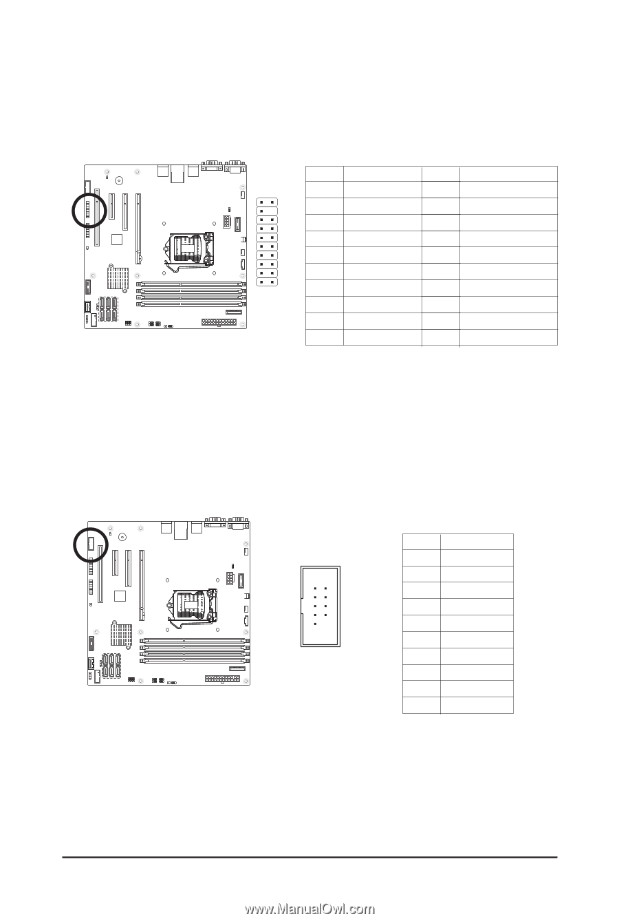
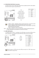
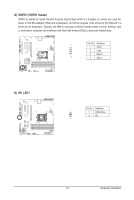
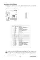
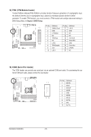
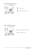
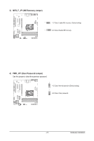
15) TPM1 (TPM Module Header) Trusted Platform Module(TPM) Platform provides function forsecure generation of cryptographic keys, the ability to limit the use of cryptographic keys, aswell as a hardware pseudo-random number generator. To enable TPM function, you must connect a TPM module and configre advanced setting in BIOS Setup Menu in Chapter 2 BIOS Setup. Pin No. Definition Pin No. Definition 12 1 33MHz Clock 11 LAD 0 2 GND 11 GND 3 LFRAME# 13 NC 4 NC 14 NC 5 TPM Rest 15 3.3V AUX 6 NC 16 Serial IRQ 19 20 7 LAD3 17 GND 8 TPM Disable 18 Clock Run 9 3.3V 19 LPCPD 10 LAD 1 20 NC 16) COM2 (Serial Port Header) The COM header can provide one serial port via an optional COM port cable. For purchasing the optional COM port cable, please contact the local dealer. 12 9 10 Pin No. 1 2 3 4 5 6 7 8 9 10 Definition NDCDNSIN NSOUT NDTRGND NDSRNRTSNCTSNRINo Pin Hardware Installation - 24 -
-
 1
1 -
2
-
3
-
4
-
5
-
6
-
7
-
8
-
9
-
10
-
11
-
12
-
13
-
14
-
15
-
16
-
17
-
18
-
 19
19 -
 20
20 -
 21
21 -
 22
22 -
 23
23 -
 24
24 -
 25
25 -
 26
26 -
 27
27 -
 28
28 -
 29
29 -
30
-
31
-
32
-
33
-
34
-
35
-
36
-
37
-
38
-
39
-
40
-
41
-
42
-
43
-
44
-
45
-
46
-
47
-
48
-
49
-
50
-
51
-
52
-
53
-
54
-
55
-
56
-
57
-
58
-
59
 |
 |