Gigabyte GA-6UASL1 Manual - Page 20
SATA0/1/2/3/4/5 SATA 3Gb/s Connectors, USB1 USB Headers
 |
View all Gigabyte GA-6UASL1 manuals
Add to My Manuals
Save this manual to your list of manuals |
Page 20 highlights
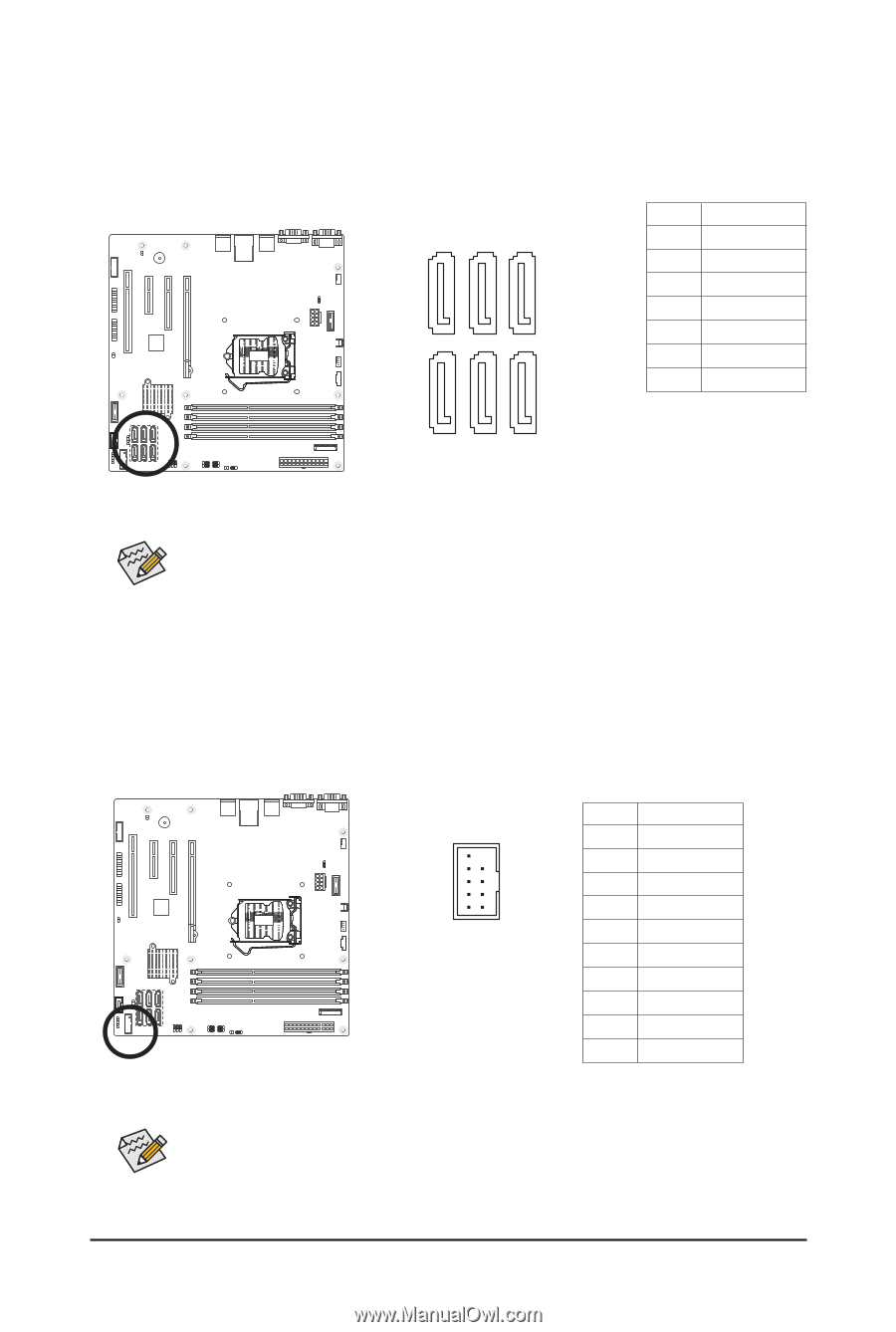
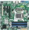
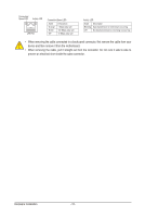
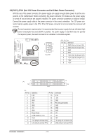
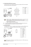
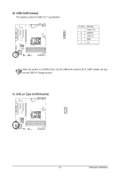
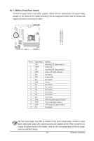
PORT PORT PORT 8) SATA0/1/2/3/4/5 (SATA 3Gb/s Connectors) The SATA connectors conform to SATA 3Gb/s standard and are compatible with SATA 1.5Gb/s standard. Each SATA connector supports a single SATA device. SATA4 SATA2 SATA0 1 G.QBOFM Pin No. 1 2 3 4 5 6 7 Definition GND TXP TXN GND RXN RXP GND 7 SATA5 SATA3 SATA0 (Note) • A RAID 0 or RAID 1 configuration requires at least two hard drives. If more than two hard drives are configured, the total number of hard drives must be an even number. • A RAID 5 configuration requires at least three hard drives. (The total number of hard drives does not have to be an even number.) • A RAID 10 configuration requires four hard drives. When a RAID configuration is built across the SATA 3Gb/s channels, the system performance of the RAID configuration may vary depends on the devices are connected. 9) USB1 (USB Headers) The headers conform to USB 2.0/1.1 specification. Each USB header can provide two USB ports via an optional USB bracket. For purchasing the optional USB bracket, please contact the local dealer. 10 9 Pin No. Definition 1 Power (5V) 2 Power (5V) 3 USB DX- 4 USB DY- 21 5 USB DX+ 6 USB DY+ 7 GND 8 GND 9 No Pin 10 OC When the system is in S4/S5 mode, only the USB ports routed to the F_USB1 header can support the ON/OFF Charge function. Hardware Installation - 20 -
-
 1
1 -
2
-
3
-
4
-
5
-
6
-
7
-
8
-
9
-
10
-
11
-
12
-
13
-
14
-
 15
15 -
 16
16 -
 17
17 -
 18
18 -
 19
19 -
 20
20 -
 21
21 -
 22
22 -
 23
23 -
 24
24 -
 25
25 -
26
-
27
-
28
-
29
-
30
-
31
-
32
-
33
-
34
-
35
-
36
-
37
-
38
-
39
-
40
-
41
-
42
-
43
-
44
-
45
-
46
-
47
-
48
-
49
-
50
-
51
-
52
-
53
-
54
-
55
-
56
-
57
-
58
-
59
 |
 |