Gigabyte GA-Z170X-SOC User Manual - Page 32
M2C_32G/M2D_32G/M2A_32G M.2 Socket 3 Connectors, Slide the M.2 SSD into the connector at an angle.
 |
View all Gigabyte GA-Z170X-SOC manuals
Add to My Manuals
Save this manual to your list of manuals |
Page 32 highlights
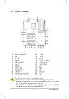
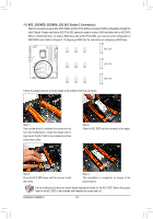
_ B S_ B B 11) M2C_32G/M2D_32G/M2A_32G (M.2 Socket 3 Connectors) The M.2 connectors support M.2 SATA SSDs and M.2 PCIe SSDs and support RAID configuration through the S _ B_B Intel® Chipset. Please note that an M.2 PCBIeSBS_ SD cannot be used to create a RAID set either with an M.2 SATA BSSD or a SATA hard drive. To create a RAID array with an M.2 PCIe SSD, you must set up the configuration in UEFI BIOS mode. Refer to Chapter 3, "Configuring a RAID Set," for instructions on configuring a RAISSD array. _ S B_B _B S S_ _ B S B_ _B S S____BBU B S_ B 80C 60C 42C 80D 60D 42D F M2C_32G S S M2D_32G S S M2A_32G _S 80A 60A 42A F_UFSoBS__l3_l_oBBUFw the steps below to correctly install an M.2 SSD in the M.2Fconnector. _0 F_USB_3 UF _ F B _0 _F F_USB3 F Step 1: Use a screw driver to unfasten the screw and nut from the motherboard. Locate the proper mounting hole for the M.2 SSD to be installed and then screw the nut first. S_te0p 2: S_lidFe the M.2 SSD into the connector at an angle. _0 F _F _0 F _0 F Step 3: Press the M.2 SSD down and then secure it with the screw. Step 4: The installation is completed, as shown in the picture above. On the motherboard there are three length adjustment holes for the M.2 SSD. Select the proper hole for the M.2 SSD to be installed and refasten the screw and nut. Hardware Installation - 32 -
-
 1
1 -
2
-
3
-
4
-
5
-
6
-
7
-
8
-
9
-
10
-
11
-
12
-
13
-
14
-
15
-
16
-
17
-
18
-
19
-
20
-
21
-
22
-
23
-
24
-
25
-
26
-
 27
27 -
 28
28 -
 29
29 -
 30
30 -
 31
31 -
 32
32 -
 33
33 -
 34
34 -
 35
35 -
 36
36 -
 37
37 -
38
-
39
-
40
-
41
-
42
-
43
-
44
-
45
-
46
-
47
-
48
-
49
-
50
-
51
-
52
-
53
-
54
-
55
-
56
-
57
-
58
-
59
-
60
-
61
-
62
-
63
-
64
-
65
-
66
-
67
-
68
-
69
-
70
-
71
-
72
-
73
-
74
-
75
-
76
-
77
-
78
-
79
-
80
-
81
-
82
-
83
-
84
-
85
-
86
-
87
-
88
-
89
-
90
-
91
-
92
-
93
-
94
-
95
-
96
-
97
-
98
-
99
-
100
-
101
-
102
-
103
-
104
-
105
-
106
-
107
-
108
-
109
-
110
-
111
-
112
-
113
-
114
-
115
-
116
-
117
-
118
-
119
-
120
-
121
-
122
-
123
-
124
-
125
-
126
-
127
-
128
-
129
-
130
-
131
-
132
 |
 |
