HP 11kVA HP Monitored Power Distribution Unit User Guide - Page 22
Grounding the PDU
 |
View all HP 11kVA manuals
Add to My Manuals
Save this manual to your list of manuals |
Page 22 highlights
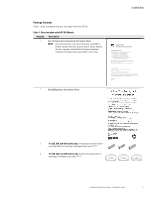
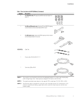
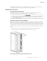
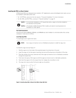
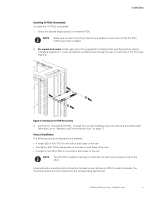
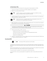
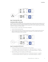
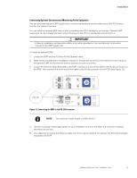
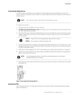
Installation Installing Enterprise PDUs To install the Enterprise PDU vertically with mounting buttons directly attached to the PDU: 1. Locate the two keyhole mounting buttons and 8-32 installation screws (supplied). 2. Decide how to orient the PDU in the rack. NOTE The PDU orientation you choose will determine whether you install the mounting buttons on the back, left side, or right side of the PDU. 3. Using the supplied 8-32 screws and a Phillips screwdriver, secure the top and bottom mounting buttons on the back, left side, or right side of the PDU. NOTE Make sure the screw is completely seated in the mounting button so that it is not protruding from the recessed button mounting hole. 4. Before attempting to mount the PDU or PDUs, locate the keyhole slots on the rack post that correspond with the position of the top and bottom mounting buttons. CAUTION Use great care in handling the PDU in the following steps. Avoid contact between the PDU and the rack because there is a risk of damage to the PDU or the rack. 5. Install the Enterprise PDU or PDUs in the rack: - Carefully move the PDU into position against the rail. - Insert the top and bottom mounting buttons into the appropriate keyhole slots. - Push down to secure the PDU in position. - Repeat with any additional PDUs. 6. Continue to "Grounding the PDU"if you are installing a ground screw and grounding cable. Otherwise, go to "Network and Environmental Ports" on page 17. Grounding the PDU NOTE Grounding the PDU is optional but recommended. Conductors can be connected to the ground screw for functional grounding or bonding of ungrounded metal parts within the rack. The grounding screw is sized to safely conduct the fault current of the single largest output breaker. Neither the earth bonding screw nor the surface of the chassis around the screw is painted. This ensures that the screw and washers make contact with bare metal, not a painted surface. The ground symbol is impressed in the chassis above the earth bonding screw. To ground the PDU, connect a grounding cable (not supplied) from earth to the grounding screw shown in Figure 9. HP Monitored PDU User's Guide P-164000281-Rev 1 16
-
 1
1 -
2
-
3
-
4
-
5
-
6
-
7
-
8
-
9
-
10
-
11
-
12
-
13
-
14
-
15
-
16
-
 17
17 -
 18
18 -
 19
19 -
 20
20 -
 21
21 -
 22
22 -
 23
23 -
 24
24 -
 25
25 -
 26
26 -
 27
27 -
28
-
29
-
30
-
31
-
32
-
33
-
34
-
35
-
36
-
37
-
38
-
39
-
40
-
41
-
42
-
43
-
44
-
45
-
46
-
47
-
48
-
49
-
50
-
51
-
52
-
53
-
54
-
55
-
56
-
57
-
58
-
59
-
60
-
61
-
62
-
63
-
64
-
65
-
66
-
67
-
68
-
69
-
70
-
71
-
72
-
73
-
74
-
75
-
76
-
77
-
78
-
79
-
80
-
81
-
82
-
83
-
84
-
85
-
86
-
87
-
88
-
89
-
90
-
91
-
92
-
93
-
94
-
95
-
96
-
97
-
98
-
99
-
100
-
101
-
102
-
103
-
104
-
105
-
106
-
107
-
108
-
109
-
110
-
111
-
112
-
113
-
114
-
115
-
116
-
117
-
118
-
119
-
120
 |
 |
