HP 17-bs000 Maintenance and Service Guide - Page 78
and right sides, the display bezel until the bezel disengages from the display enclosure.
 |
View all HP 17-bs000 manuals
Add to My Manuals
Save this manual to your list of manuals |
Page 78 highlights
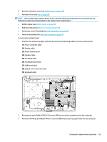
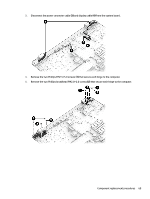
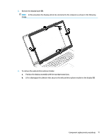
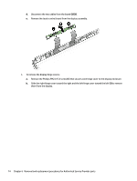
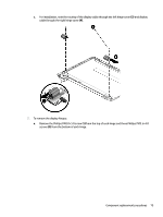
6. Remove the display cable routing guide from the display enclosure. 7. Open the display to rotate the hinges upward to an angle (1). 8. Separate the display assembly from the computer (2). If it is necessary to replace any of the display assembly subcomponents: 1. Flex the inside of the top edge (1), left (2) and right sides (3), and the inside of the bottom edge (4) of the display bezel until the bezel disengages from the display enclosure. 70 Chapter 6 Removal and replacement procedures for Authorized Service Provider parts
-
 1
1 -
2
-
3
-
4
-
5
-
6
-
7
-
8
-
9
-
10
-
11
-
12
-
13
-
14
-
15
-
16
-
17
-
18
-
19
-
20
-
21
-
22
-
23
-
24
-
25
-
26
-
27
-
28
-
29
-
30
-
31
-
32
-
33
-
34
-
35
-
36
-
37
-
38
-
39
-
40
-
41
-
42
-
43
-
44
-
45
-
46
-
47
-
48
-
49
-
50
-
51
-
52
-
53
-
54
-
55
-
56
-
57
-
58
-
59
-
60
-
61
-
62
-
63
-
64
-
65
-
66
-
67
-
68
-
69
-
70
-
71
-
72
-
 73
73 -
 74
74 -
 75
75 -
 76
76 -
 77
77 -
 78
78 -
 79
79 -
 80
80 -
 81
81 -
 82
82 -
 83
83 -
84
-
85
-
86
-
87
-
88
-
89
-
90
-
91
-
92
-
93
-
94
-
95
-
96
-
97
-
98
-
99
-
100
-
101
-
102
-
103
-
104
-
105
-
106
-
107
-
108
-
109
-
110
-
111
-
112
-
113
-
114
 |
 |
6.
Remove the display cable routing guide from the display enclosure.
7.
Open the display to rotate the hinges upward to an angle
(1)
.
8.
Separate the display assembly from the computer
(2)
.
If it is necessary to replace any of the display assembly subcomponents:
1.
Flex the inside of the top edge
(1)
, left
(2)
and right sides
(3)
, and the inside of the bottom edge
(4)
of
the display bezel until the bezel disengages from the display enclosure.
70
Chapter 6
Removal and replacement procedures for Authorized Service Provider parts