HP 17-bs000 Maintenance and Service Guide - Page 85
and display/webcam cable routing bracket
 |
View all HP 17-bs000 manuals
Add to My Manuals
Save this manual to your list of manuals |
Page 85 highlights
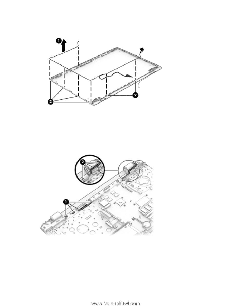
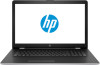
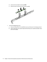
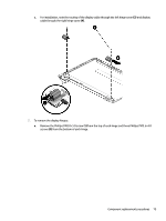
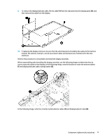
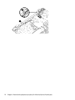
9. To remove the display/webcam cable, lift the cable (1) from the clips built into the display panel (2), and then remove the cable from the display. 10. If replacing the display enclosure, be sure that the subcomponents (including the webcam/microphone module, the antenna receivers, and all associated cables and hardware) are transferred to the new enclosure. Reverse this procedure to reassemble and install the display assembly. When reassembling and reinstalling the display assembly, use the following images to determine how to correct route the cables in the display. In the following image, note the location to route the antenna cables (1) and display/webcam cable routing bracket (2). In the following image, note the correctly routed antenna cables (1) and display/webcam cable (2). Component replacement procedures 77
-
 1
1 -
2
-
3
-
4
-
5
-
6
-
7
-
8
-
9
-
10
-
11
-
12
-
13
-
14
-
15
-
16
-
17
-
18
-
19
-
20
-
21
-
22
-
23
-
24
-
25
-
26
-
27
-
28
-
29
-
30
-
31
-
32
-
33
-
34
-
35
-
36
-
37
-
38
-
39
-
40
-
41
-
42
-
43
-
44
-
45
-
46
-
47
-
48
-
49
-
50
-
51
-
52
-
53
-
54
-
55
-
56
-
57
-
58
-
59
-
60
-
61
-
62
-
63
-
64
-
65
-
66
-
67
-
68
-
69
-
70
-
71
-
72
-
73
-
74
-
75
-
76
-
77
-
78
-
79
-
 80
80 -
 81
81 -
 82
82 -
 83
83 -
 84
84 -
 85
85 -
 86
86 -
 87
87 -
 88
88 -
 89
89 -
 90
90 -
91
-
92
-
93
-
94
-
95
-
96
-
97
-
98
-
99
-
100
-
101
-
102
-
103
-
104
-
105
-
106
-
107
-
108
-
109
-
110
-
111
-
112
-
113
-
114
 |
 |