HP 17-bs000 Maintenance and Service Guide - Page 81
that secure the touch control board to the top of the, Remove the two Phillips PM2.0×2.0 screws
 |
View all HP 17-bs000 manuals
Add to My Manuals
Save this manual to your list of manuals |
Page 81 highlights
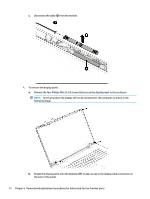
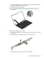
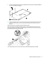
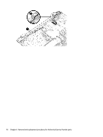
c. On the back of the display panel, release the adhesive strip that secures the display panel cable to the display panel (2), and then disconnect the cable (3). d. Remove the display panel from the computer. NOTE: In this procedure the display will not be connected to the computer as shown in the following image. 5. To remove the touch control board from the display: a. Remove the two Phillips PM2.0×2.0 screws (1) that secure the touch control board to the top of the display assembly. b. Lift the board away from the display (2) enough to access the cables underneath. c. Rotate the board upside down to access the connectors underneath (1). Component replacement procedures 73
-
 1
1 -
2
-
3
-
4
-
5
-
6
-
7
-
8
-
9
-
10
-
11
-
12
-
13
-
14
-
15
-
16
-
17
-
18
-
19
-
20
-
21
-
22
-
23
-
24
-
25
-
26
-
27
-
28
-
29
-
30
-
31
-
32
-
33
-
34
-
35
-
36
-
37
-
38
-
39
-
40
-
41
-
42
-
43
-
44
-
45
-
46
-
47
-
48
-
49
-
50
-
51
-
52
-
53
-
54
-
55
-
56
-
57
-
58
-
59
-
60
-
61
-
62
-
63
-
64
-
65
-
66
-
67
-
68
-
69
-
70
-
71
-
72
-
73
-
74
-
75
-
 76
76 -
 77
77 -
 78
78 -
 79
79 -
 80
80 -
 81
81 -
 82
82 -
 83
83 -
 84
84 -
 85
85 -
 86
86 -
87
-
88
-
89
-
90
-
91
-
92
-
93
-
94
-
95
-
96
-
97
-
98
-
99
-
100
-
101
-
102
-
103
-
104
-
105
-
106
-
107
-
108
-
109
-
110
-
111
-
112
-
113
-
114
 |
 |
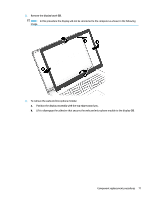
c.
On the back of the display panel, release the adhesive strip that secures the display panel cable to
the display panel
(2)
, and then disconnect the cable
(3)
.
d.
Remove the display panel from the computer.
NOTE:
In this procedure the display will not be connected to the computer as shown in the
following image.
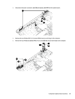
5.
To remove the touch control board from the display:
a.
Remove the two Phillips PM2.0×2.0 screws
(1)
that secure the touch control board to the top of the
display assembly.
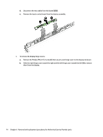
b.
Lift the board away from the display
(2)
enough to access the cables underneath.
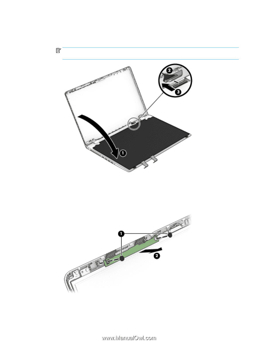
c.
Rotate the board upside down to access the connectors underneath
(1)
.
Component replacement procedures
73